
Translational thrust system for a rotary wing aircraft

a technology of translational thrust and propeller, which is applied in the direction of rotors, marine propulsion, vessel construction, etc., can solve the problems of high-speed rotary-wing aircraft, conventional variable-pitch propeller systems and variable-pitch propeller systems common to fixed-wing aircraft are unsuitable for translational thrust systems. achieve the effect of high degree of pitch angle confiden

Active Publication Date: 2010-07-20
SIKORSKY AIRCRAFT CORP
View PDF15 Cites 38 Cited by
  • Summary
  • Abstract
  • Description
  • Claims
  • Application Information

AI Technical Summary

Benefits of technology

The system provides stable and confident pitch angle control of propeller blades, ensuring steady torque and thrust production, reducing the risk of torsional instability and allowing for precise thrust management across various flight regimes.

Problems solved by technology

Variable pitch propellers common to fixed wing aircraft are unsuitable for the translational thrust system of a high speed rotary-wing aircraft as a propeller governor controls engine RPM by pitch change of the propeller blades.
Conventional variable pitch propeller systems are unsuitable for such independent operation.
Conventional variable pitch propeller systems efficiently convert rotary motion into propulsive thrust, however, conventional variable pitch propeller systems utilize a conventional propeller governor which results in at least two problems for a high-speed rotary-wing aircraft.
The second problem is potential interplay between the ECU and the propeller governor.
With both controllers acting to increase the speed of the system, the response may be greater than either had anticipated, and an overshoot will result.
With two separate controllers trying to maintain RPM, there is the potential for development of a torsional instability.

Method used


Image

  • Translational thrust system for a rotary wing aircraft
  • Translational thrust system for a rotary wing aircraft
  • Translational thrust system for a rotary wing aircraft

Examples


Embodiment Construction

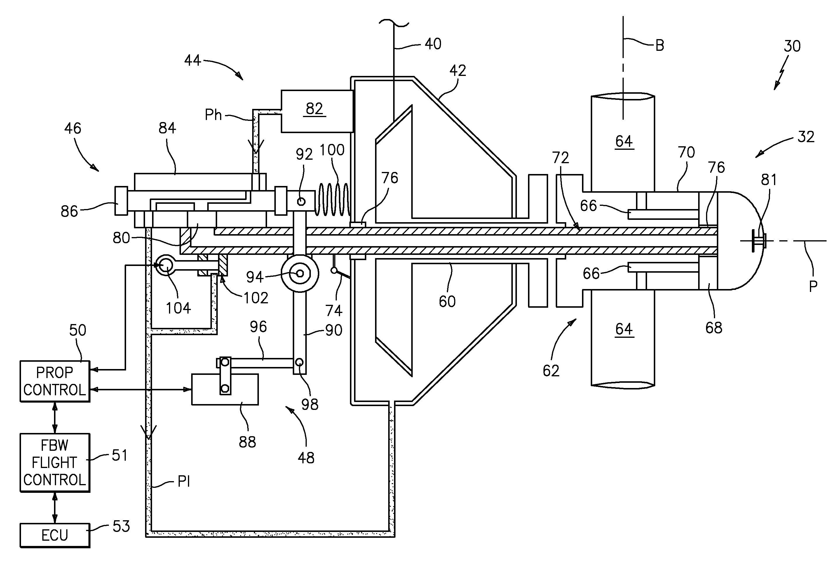
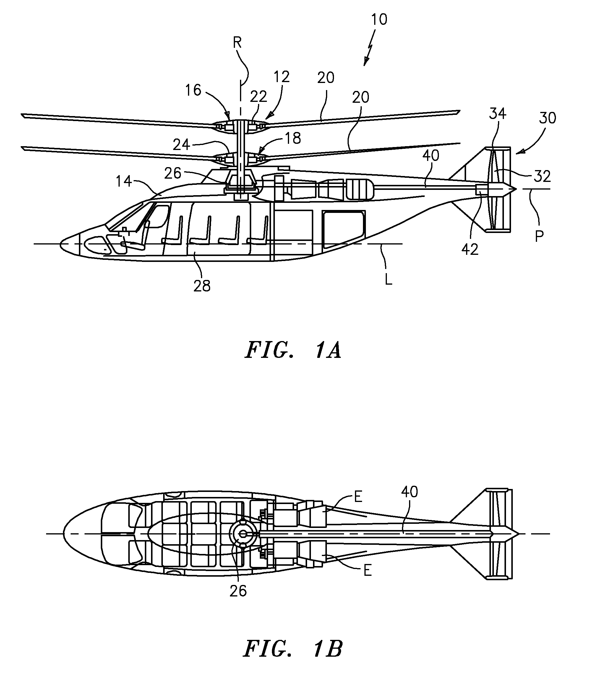
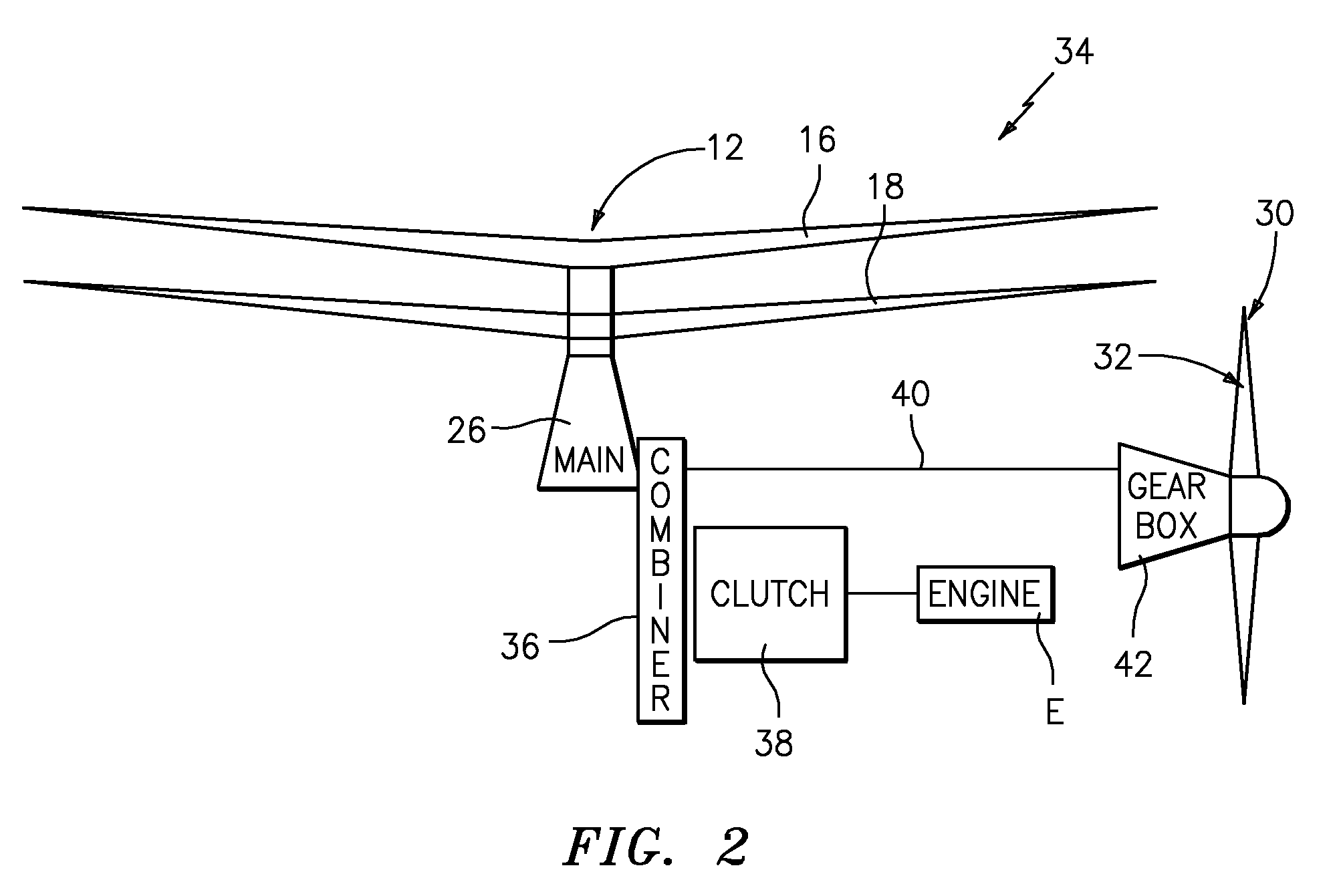
[0025]FIGS. 1A-1B illustrates a vertical takeoff and landing (VTOL) high speed compound or coaxial contra-rotating rigid rotor aircraft 10 having a dual, contra-rotating, coaxial main rotor system 12, which rotates about a rotor axis of rotation A. The aircraft 10 includes an airframe 14 which supports the dual, contra-rotating, coaxial main rotor system 12 as well as a translational thrust system 30 which provides translational thrust generally parallel to an aircraft longitudinal axis L. It should be understood that other aircraft configurations will benefit from the present invention.

[0026]The main rotor system 12 includes a first rotor system 16 and a second rotor system 18 each rotor system 16, 18 includes a multiple of rotor blades 20 mounted to a rotor hub 22, 24. The main rotor system 12 is driven by a main gearbox 26. The translational thrust system 30 may be any propeller system including, but not limited to a pusher propeller, a tractor propeller, a nacelle mounted propel...


PUM


Abstract

A translational thrust system for a high speed rotary-wing aircraft includes a propeller system driven by a propeller gearbox, a hydraulic system, and a mechanical-hydraulic control system. The mechanical-hydraulic control system utilizes a hydraulic fluid which travels to and from a propeller dome via an oil transfer / position feedback tube which translates with a propeller pitch change piston. Translation of the oil transfer / position feedback tube and the propeller pitch change piston pitches the blades between high (coarse) and low (fine) pitch positions.

Description

BACKGROUND OF THE INVENTION[0001]The present invention relates to a propeller system, and more particularly to a translational thrust system with a propeller pitch change system which integrates thrust control with a Fly-By-Wire (FBW) system of a high-speed rotary-wing aircraft.[0002]A rotary wing aircraft with a coaxial contra-rotating rotor system is capable of higher speeds compared to conventional single rotor helicopters due in part to the balance of lift between the advancing sides of the main rotor blades on the upper and lower rotor systems. To still further increase airspeed, supplemental translational thrust is provided by a translational thrust system such as a propeller system oriented substantially horizontal and parallel to the aircraft longitudinal axis to provide thrust for high-speed flight.[0003]Variable pitch propellers are common in fixed wing aircraft. These propellers are generally attached directly to the crankshaft of a reciprocating engine, or are mated to a...

Claims


Application Information

Patent Timeline
Patent Type & Authority Patents(United States)
IPC IPC(8): B63H3/04B64D35/06
CPCB64C11/38B64C27/10B64C27/14B64C2027/8236B64C2027/8254
Inventor COTTON, BRYAN S.ARIFIAN, KENNETH C.SCHWEIZER, LESLIECEVETTE, JEFFREY L.
Owner SIKORSKY AIRCRAFT CORP
Learn More