Disassembly method and reuse method of substrate mounting member

a technology of substrate mounting and disassembly method, which is applied in the direction of photosensitive materials, instruments, processed materials, etc., can solve the problems of affecting the quality of substrate mounting, so as to reduce the quantity of waste and reduce the cost

Active Publication Date: 2010-07-27
NGK INSULATORS LTD
View PDF11 Cites 6 Cited by
  • Summary
  • Abstract
  • Description
  • Claims
  • Application Information

AI Technical Summary

Benefits of technology

[0010]In this connection, it is an object of the present invention to provide a disassembly method of the substrate mounting member, which separates the base member and the electrostatic chuck in a short time without scratching the base member and the like, and to provide a reuse method of the substrate mounting member, which bonds the separated base member and electrostatic chuck to each other one more time.
[0011]In order to achieve the above-described object, a disassembly method of a substrate mounting member according to the present invention is a disassembly method of a substrate mounting member, including: heating up a substrate mounting member formed by bonding an electrostatic chuck and a base member to each other through an organic adhesive layer to a thermal decomposition temperature within a range from a thermal decomposition temperature to thermal decomposition ending temperature of the organic adhesive layer, and softening and decomposing the organic adhesive layer; and applying a separation load to the electrostatic chuck and the base member in a direction of pulling the electrostatic chuck and the base member apart from each other, thereby separating the electrostatic chuck and the base member from each other.
[0013]According to the disassembly method of a substrate mounting member according to the present invention, the electrostatic chuck and the base member can be separated from each other in an extremely short time without scratching the base member and the like.
[0014]Specifically, in the conventional method for immersing the substrate mounting member in the organic solvent, it has been extremely difficult to separate the electrostatic chuck and the base member from each other even if the substrate mounting member is immersed into the organic solvent over a day and a night. However, according to the present invention, the organic adhesive layer can be peeled off in an extremely short time. Moreover, according to the present invention, characteristics and dimensions of the electrostatic chuck and the base member are not deteriorated, and accordingly, the separated electrostatic chuck and base member can be reused as they are.
[0015]Moreover, according to the reuse method of a substrate mounting member according to the present invention, the expensive substrate mounting member is not scrapped, and accordingly, cost can be reduced, and in addition, a quantity of waste can be reduced.

Problems solved by technology

However, in such a disassembly method using the organic solvent in the above-described related art, there has been a problem that, since the organic solvent is difficult to permeate into the organic adhesive layer, it takes an extremely long time to dissolve the organic adhesive layer.
However, in this method, there is an apprehension that the base member formed of an aluminum alloy or the like may be scratched, and accordingly, this method has not been preferable.

Method used


Image

  • Disassembly method and reuse method of substrate mounting member
  • Disassembly method and reuse method of substrate mounting member
  • Disassembly method and reuse method of substrate mounting member

Examples


first embodiment

[0023]First, a description will be made of a first embodiment according to the present invention.

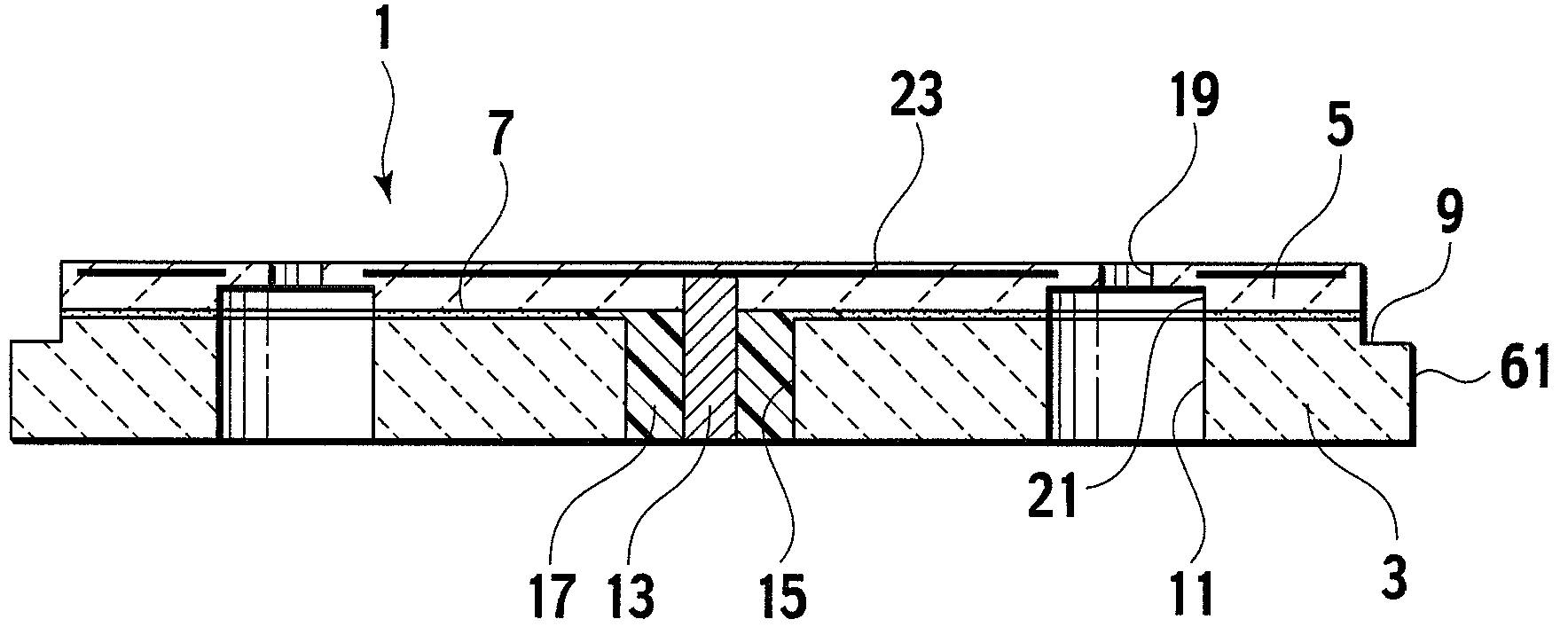
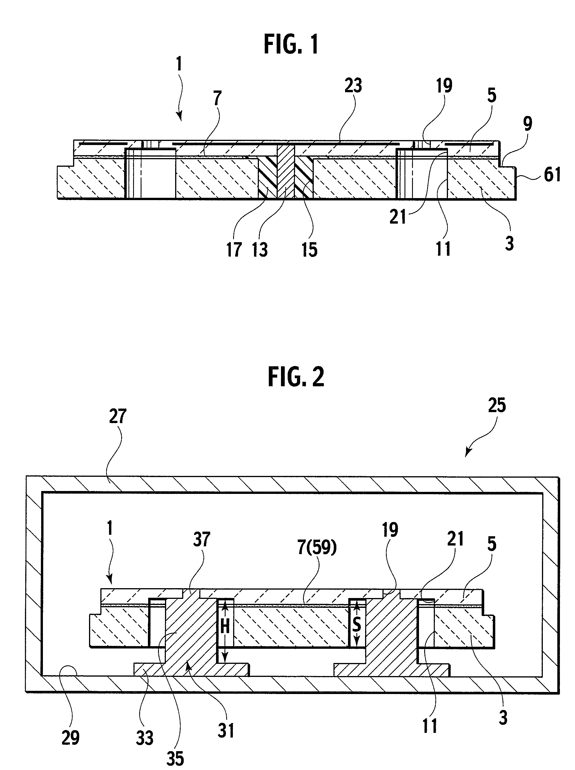
[0024]As shown in FIG. 1, a substrate mounting member 1 according to this embodiment includes a base member 3 made of aluminum, an aluminum alloy, or the like, an electrostatic chuck 5 which holds a semiconductor wafer, and an organic adhesive layer 7 which bonds the base member 3 and the electrostatic chuck 5 to each other. Specifically, the substrate mounting member 1 is a member formed by bonding the base member 3 and the electrostatic chuck 5 to each other through the organic adhesive layer 7.

[0025]The base member 3 has a disc-like outer shape, in which a step difference portion 9 is formed on an upper end portion of an outer circumferential surface 61. Moreover, a plurality of housing holes 11 which house a support plate (not shown) for lift pins therein are formed at an equal interval along a circumferential direction so as to penetrate the base member 3 in a plate thickness direct...

second embodiment

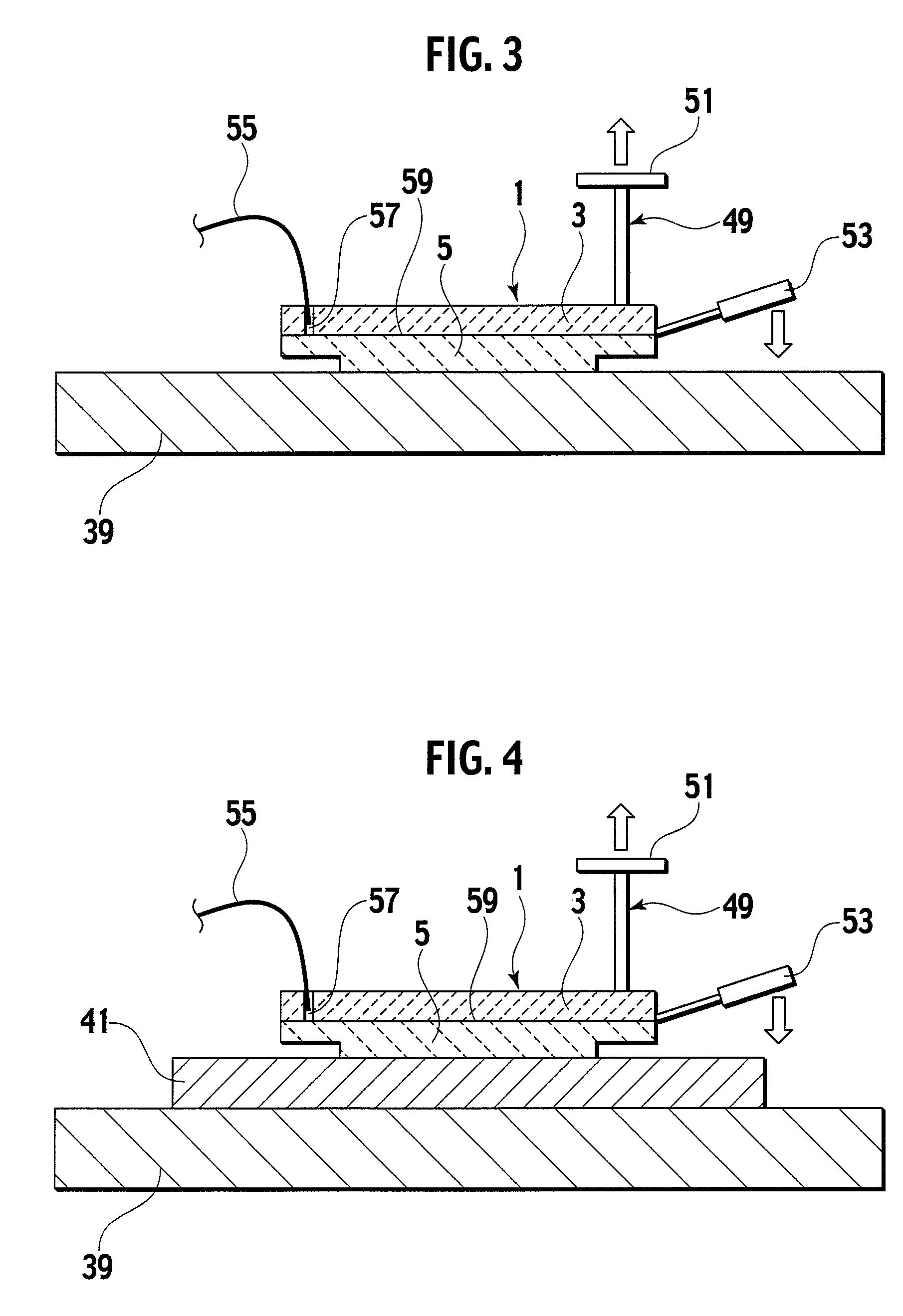
[0063]In the above-described first embodiment, the description has been made of the disassembly method for separating the base member 3 from the substrate mounting member 1. In a second embodiment, a description will be made of a method for reusing the separated electrostatic chuck 5 and base member 3.

[0064]In some case, the residue of the organic adhesive layer 7 is partially adhered onto the bonding surface of at least either the electrostatic chuck 5 or the base member 3, which as been separated from each other in the first embodiment. In this case, it is preferable to dissolve the residue by immersing the residue into the organic solvent, or to scrape off the residue by using the pallet and the like.

[0065]Subsequently, the separated base member 3 and electrostatic chuck 5 are bonded to each other by using the adhesive or the bonding sheet, thus making it possible to reuse the bonded base member 3 and electrostatic chuck 5 as a new substrate mounting member 1.

example 1

[0067]As shown in FIG. 1, the substrate mounting member 1 for use in Example 1 is a member formed by bonding the base member 3 made of aluminum and the electrostatic chuck 5 made of aluminum nitride to each other through the organic adhesive layer 7. Three lift pin holes 19 were drilled in the electrostatic chuck 5 along the circumferential direction thereof, and the spot facing portions 21 were formed on the lower portions of the lift pin holes 19. A weight of the base member 3 was 3400 g. Moreover, with regard to the type of the organic adhesive layer 7, as shown in Table 1, thermosetting acrylic resin, thermosetting silicon resin, thermosetting polyimide resin, thermosetting epoxy resin, thermosetting acrylic resin, and thermoplastic acrylic resin were used. The thermal decomposition starting temperatures and thermal decomposition ending temperatures of the organic adhesive layers 7 made of these resins were measured. Results of the measurements were obtained as shown in Table 1....


PUM

PropertyMeasurementUnit
heightaaaaaaaaaa
temperatureaaaaaaaaaa
weightaaaaaaaaaa

Abstract

An electrostatic chuck and a base member are separated from each other while heating up a substrate mounting member to a thermal decomposition temperature within a range from a thermal decomposition starting temperature to a thermal decomposition ending temperature and then softening and decomposing an organic adhesive layer.

Description

CROSS REFERENCE TO RELATED APPLICATIONS[0001]This application is based upon and claims the benefit of priority from Japanese Patent Application No. 2005-322193, filed on Nov. 7, 2005; the entire contents of which are incorporated herein by reference.BACKGROUND OF THE INVENTION[0002]1. Field of the Invention[0003]The present invention relates to a disassembly method and reuse method of a substrate mounting member. More specifically, the present invention relates to a method for separating an electrostatic chuck and a base member, which construct the substrate mounting member, from each other. Moreover, the present invention relates to a method for reusing at least any one of the separated electrostatic chuck and base member. The substrate mounting member performs treatments such as dry etching and deposition for a substrate such as a wafer.[0004]2. Description of the Related Art[0005]In a manufacturing process of a semiconductor device and the like, in order to perform a treatment in...

Claims


Application Information

Patent Timeline
Patent Type & Authority Patents(United States)
IPC IPC(8): H01T23/00
CPCH01L21/67103H01L21/6831Y10T156/1168Y10T156/1153H01L21/68
Inventor EGUCHI, MASAHITO
Owner NGK INSULATORS LTD
Why Eureka
Try Eureka