
Specimen analysis method and specimen analysis device

a specimen analysis and specimen technology, applied in the direction of instruments, material electrochemical variables, phase/state change investigation, etc., can solve the problems of reducing the accuracy of blood glucose measurement, affecting the accuracy of sample analysis, etc., to achieve accurate finding and enhance sample analysis accuracy

Active Publication Date: 2010-07-27
ARKRAY INC
View PDF19 Cites 4 Cited by
  • Summary
  • Abstract
  • Description
  • Claims
  • Application Information

AI Technical Summary

Benefits of technology

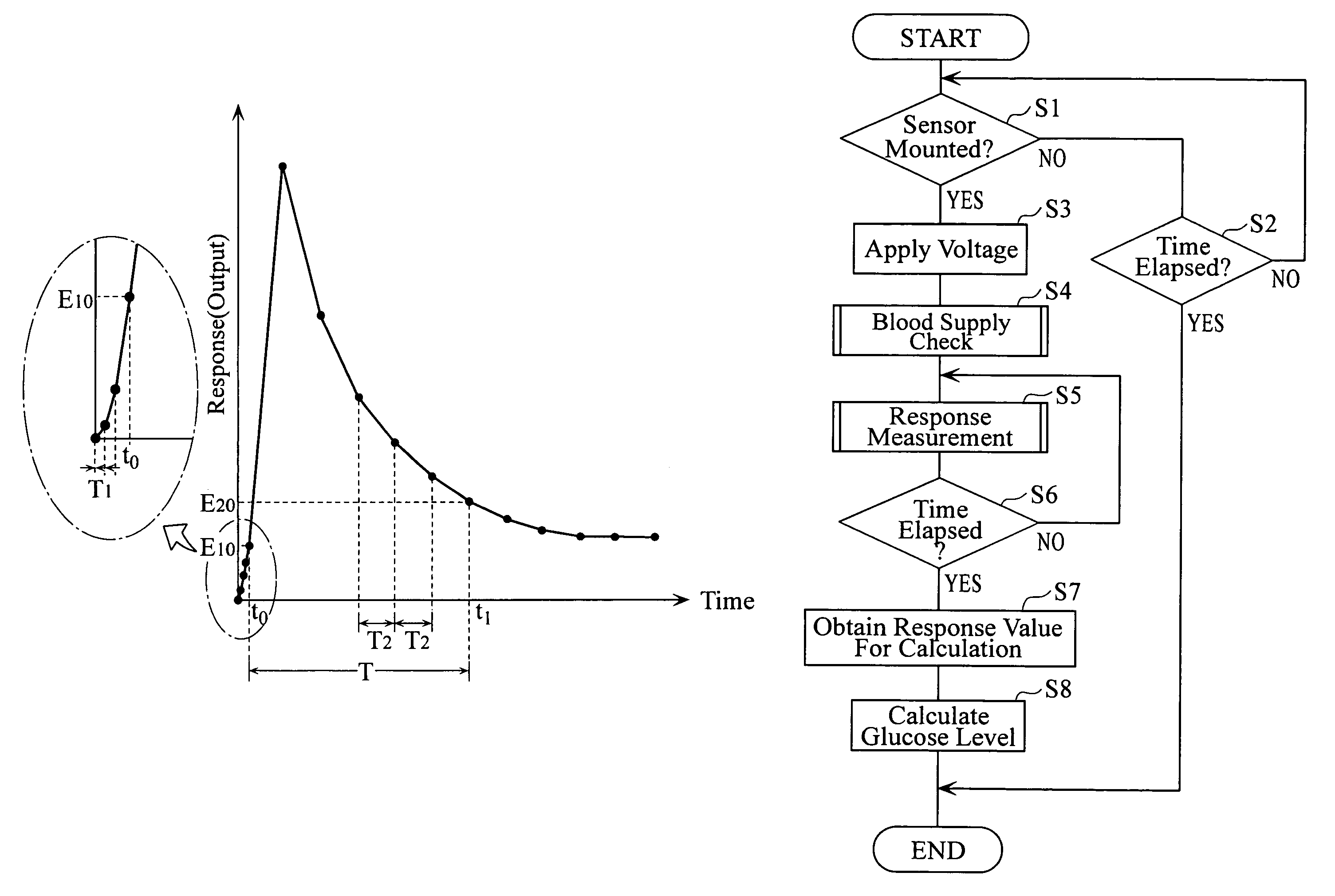
The present invention provides a method and apparatus for analyzing samples using an analytical tool. The method involves confirming the time when a sample is supplied to the analytical tool and the time when the output from the analytical tool is used for computation. This is done by using a double integration circuit that inputs and outputs a physical quantity related to the sample. The double integration circuit performs the input and output at different time intervals, and the time interval between the two is set longer after the sample is confirmed to be supplied to the analytical tool. This allows for accurate analysis of the sample by accurately finding the time when the sample is supplied and the output from the analytical tool is ready for use. The method and apparatus can be used with different types of analytical tools and samples.

Problems solved by technology

Therefore, in the case where the time interval (t) for measuring the response current is set long, the time when the blood is supplied cannot be determined accurately.
Due to such inaccuracy, the time period from when the sample is supplied till when the response current for the computation is sampled may vary among the measurements, which may degrade the measurement accuracy of the blood glucose level.

Method used


Image

  • Specimen analysis method and specimen analysis device
  • Specimen analysis method and specimen analysis device
  • Specimen analysis method and specimen analysis device

Examples


Embodiment Construction

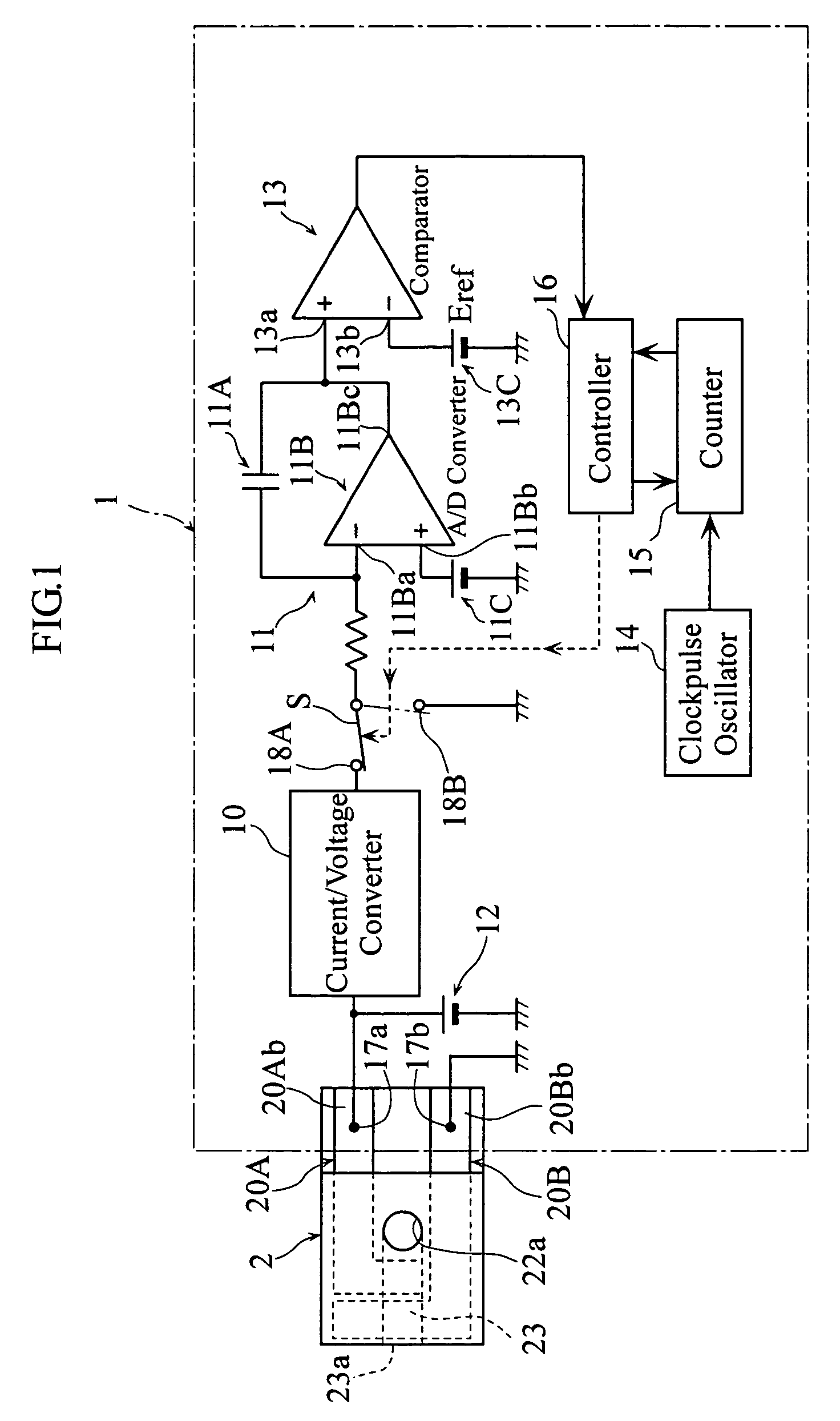
[0029]As shown in FIG. 1, the analytical apparatus 1, which is used with a biosensor 2 mounted thereto, includes a current / voltage converting circuit 10, an A / D converter 11, a circuit power source 12, a comparator 13, a clockpulse oscillator 14, a counter 15 and a control circuit 16.

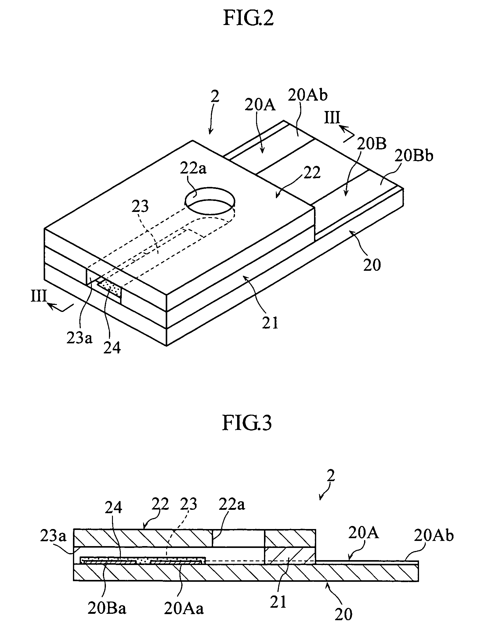
[0030]The biosensor 2 used in the analytical apparatus 1 functions to analyze a particular component contained in a sample (e.g. blood) by an electrochemical method and is designed to be disposable. As shown in FIGS. 2 through 4, the biosensor 2 comprises a substrate 20 and a cover 22 stacked thereon via a spacer 21 formed with a slit 21a. The above-described elements 20-22 define a flow path 23. The flow path 23 is provided for moving the sample introduced through a sample introduction port 23a toward a hole 22a of the cover 22 by utilizing capillary action and for providing a reaction field for the sample and a reagent.

[0031]The substrate 20 is formed with a working electrode 20A and a counter electro...


PUM

PropertyMeasurementUnit
sampling time intervalaaaaaaaaaa
charge timeaaaaaaaaaa

Abstract

The present invention relates to a technique for analyzing a sample by utilizing a double integration circuit (11) for outputting a physical quantity related to the output from an analytical tool (2). In the present invention, the time interval from when the output from the analytical tool (2) is inputted into the double integration circuit (11) till when the physical quantity is started to be outputted from the double integration circuit (11) differs before and after the supply of the sample to the analytical tool (2) is confirmed.

Description

TECHNICAL FIELD[0001]The present invention relates to a technique for analyzing a particular component (e.g. glucose, cholesterol or lactic acid) in a sample (biochemical sample such as blood or urine)BACKGROUND ART[0002]As an easy method to measure the glucose level in blood, a disposable glucose sensor is often utilized (See Patent Document 1, for example). For instance, the glucose sensor may be designed to output the response current, which is necessary for computing the blood glucose level, when it is mounted to an analytical apparatus. In the analytical apparatus, the magnitude of the response current is determined by utilizing a double integration circuit including a capacitor, and the blood glucose level is computed based on the determined response current. As shown in FIGS. 11A and 11B, the magnitude of the response current is determined based on the discharge time (T2) of the capacitor after the capacitor is charged with the electric charge related with the response curren...

Claims


Application Information

Patent Timeline
Patent Type & Authority Patents(United States)
IPC IPC(8): G01N27/27G01N33/50G01N27/06G01N27/416
CPCG01N27/3273Y10T436/144444Y10T436/115831Y10T436/11Y10T436/12Y10T436/112499G01N27/416G01N27/28
Inventor KAWAI, TAKUJI
Owner ARKRAY INC
Learn More