Fluid pressure reduction device for high pressure-drop ratios

a technology of fluid pressure reduction and drop ratio, which is applied in fluid dynamics, lighting and heating apparatus, transportation and packaging, etc., can solve the problems of high noise within the system, damage to vibration, and application may produce unacceptable levels of aerodynamic noise, so as to reduce any associated aerodynamic noise

Active Publication Date: 2010-08-03
FISHER CONTROLS INT LLC
View PDF24 Cites 21 Cited by
  • Summary
  • Abstract
  • Description
  • Claims
  • Application Information

AI Technical Summary

Benefits of technology

[0011]In an example fluid pressure reduction device, the device comprises two or more stackable annular plates, each plate having a hollow center and a perimeter aligned along a longitudinal axis when the annular plates are stacked one on top of the other. Each plate has at least one inlet flow sector having an inlet flow stage for defining a first inlet area and a first outlet area, and at least one outlet flow sector having an outlet flow stage defining a second inlet area and a second outlet area, wherein the ratio of the second inlet area to the second outlet area is predetermined to define a backpressure at the outlet flow stage to provide a subsonic fluid flow at the perimeter. The fluid pressure reduction device may provide two stages of subsonic fluid flow to substantially reduce any associated aerodynamic noise.

Problems solved by technology

In the process control industry many process applications may produce unacceptable levels of aerodynamic noise.
It is understood that the process conditions within recovery circuit produce high temperatures and large pressure differentials (e.g., 1200° F. and 500 psid) that may create damaging vibration and high levels of noise within the system as steam is redirected from the turbine.
Diffusers are aerodynamically restrictive devices that reduce fluid pressure and temperature by transferring and / or absorbing fluid energy contained in the bypass steam.
Similarly, in control valve applications, valve trim, such as cages, may also encounter harsh conditions.
It is known that during compressor operation a potentially destructive condition known as “surge” may occur.
Operation of the compressor at or below the surge point may cause unstable operation that may cause compressor surge to occur.
For example, in normal operation as gas flow through the compressor system decreases, the fluid pressure increases to maintain flow, but near the surge point, the compressor can not impart enough momentum in the gas to continue gas flow through the compressor, causing gas flow to momentarily stop.
If compressor operation continues near the surge point, the surge condition will repeat, causing repetitive flow reversals, until the process conditions change.
The flow reversals associated with compressor surge create compressor thrust reversals that can cause unstable axial and radial vibration that can damage the compressor and create high levels of noise.
When the fluid velocities approach the speed of sound, shock cells form within the fluid that contribute to unacceptably high levels of noise.
In high pressure-drop ratio applications, conventional fluid pressure reduction devices quickly experience choked flow and are not acceptable in such applications where noise level and vibration are a concern.
Unfortunately, large baffle areas are required for very high pressure-drop ratio applications and these types of baffle / attenuator devices cannot be easily placed in valve bodies for valve trim.
This approach also significantly increases the manufacturing cost of large diffusers.
Additionally, typical multi-stage fluid pressure reduction devices generally do not have enough physical structure within the housing to withstand the very high pressure drops and have been known to physically separate while under load, causing catastrophic damage to the valve body or the piping / duct system around the diffuser.
Unfortunately this technique reduces overall fluid capacity of a system or valve.
This technique is not viable in valve trim or diffusers as increases in stack height may make the structure too large to fit within valve bodies or duct work and may be too costly to manufacture.

Method used


Image

  • Fluid pressure reduction device for high pressure-drop ratios
  • Fluid pressure reduction device for high pressure-drop ratios
  • Fluid pressure reduction device for high pressure-drop ratios

Examples


Embodiment Construction

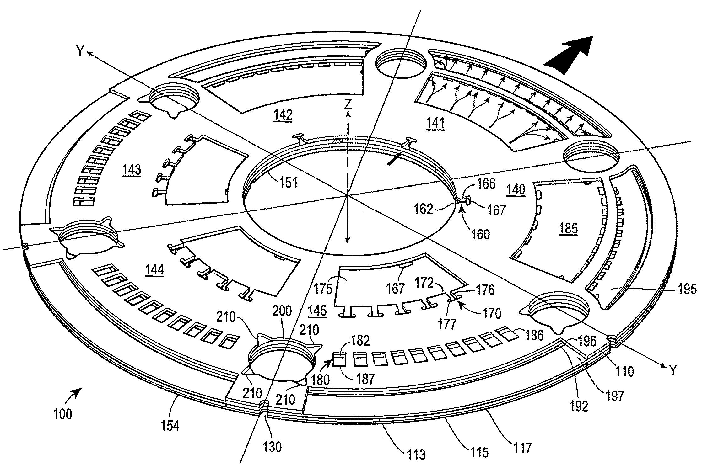
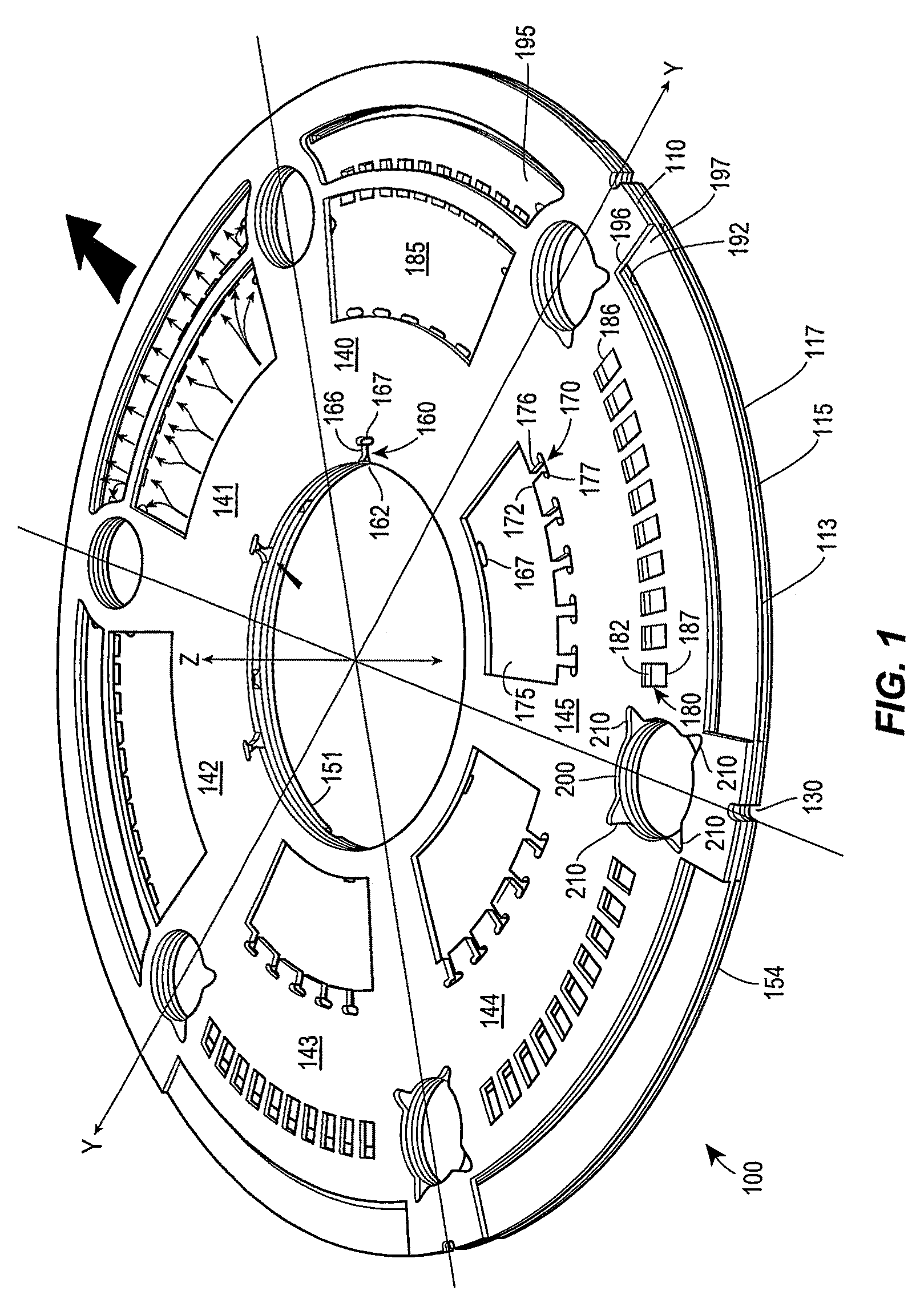
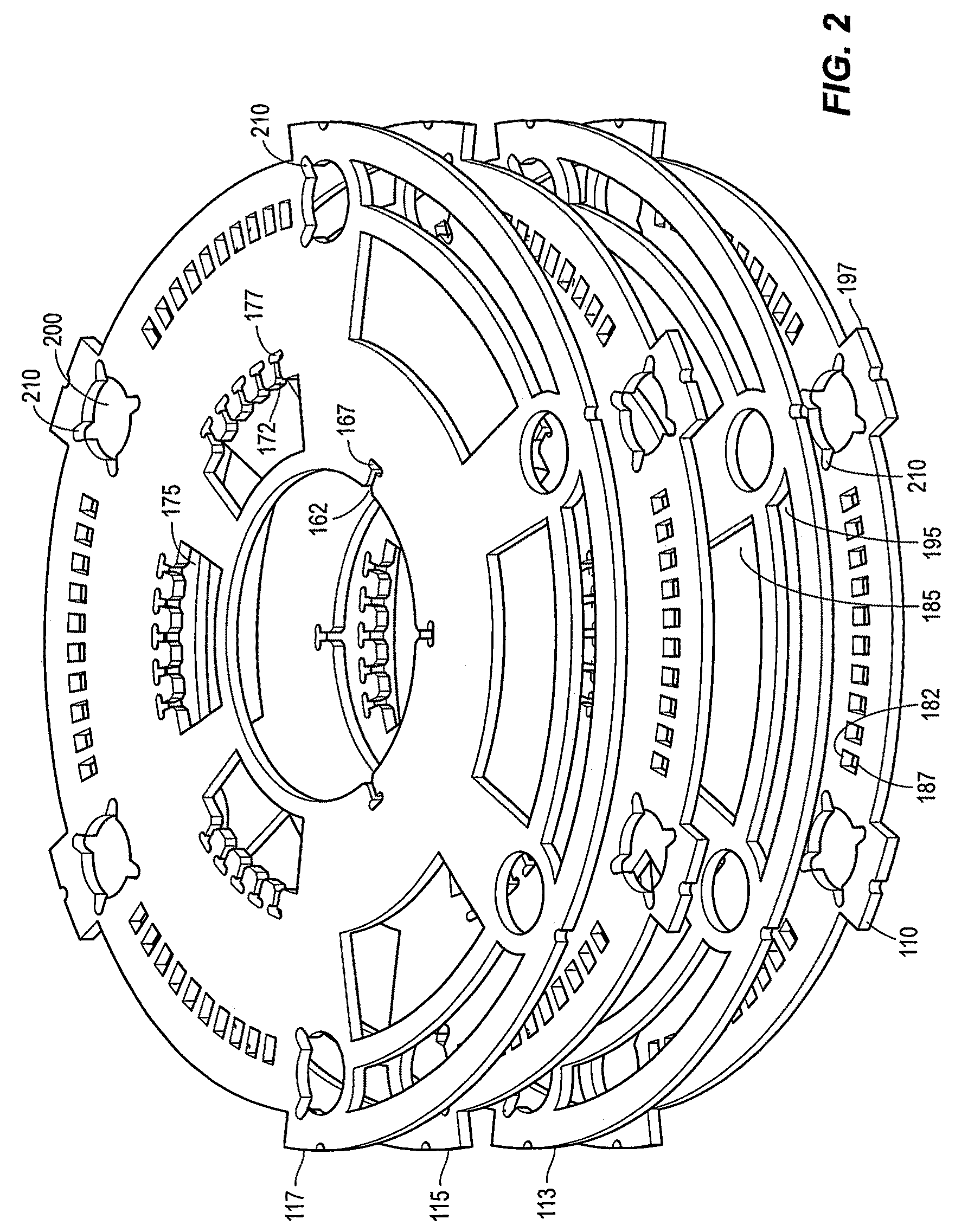
[0018]An example fluid pressure reduction device for a diffuser is shown in FIGS. 1 and 2. The example fluid pressure reduction device or diffuser uses a stack of annular plates to provide multiple pressure reduction flow paths between inlets and the outlets of the device. The stacked plate assembly may be characterized as follows: 1) the stacked plate assembly has multiple pressure reduction flow paths having inlets at a hollow center and outlets at an outer perimeter radially aligned in individual flow sectors; 2) the pressure reduction flow paths are generally radial and are defined by more than at least two pressure reduction stages coupled in series with each pressure reduction stage being coupled to at least one subsequent pressure reduction stage in an adjacent annular plate; and 3) each stage includes one or more apertures where the inner or first and second stage apertures have well-rounded or well-tapered inlet and an abrupt discharge and the outer stage or third or fourth...


PUM


Abstract

A fluid pressure reduction device comprises two or more stackable annular plates. Each disk having a perimeter and a hollow center aligned along a longitudinal axis when the annular plates are stacked one on top of the other. Each disk further comprising at least one inlet flow sector having an inlet flow stage for defining a first inlet area and a first outlet area, and at least one outlet flow sector having an outlet flow stage defining a second inlet area and a second outlet areas wherein the ratio of the second inlet area to the second outlet area is predetermined to define a backpressure at the outlet flow stage to provide a sub-sonic fluid flow at the perimeter.

Description

FIELD OF THE INVENTION[0001]This disclosure relates generally to fluid pressure reduction devices, and more particularly, to an improvement of fluid pressure reduction devices used in process control applications having high pressure-drop ratios.BACKGROUND OF THE INVENTION[0002]In the process control industry many process applications may produce unacceptable levels of aerodynamic noise. For example, modern power generating stations typically use steam turbines to generate power. The steam turbines require periodic maintenance and it is generally known to be more economical to continue steam generation during turbine maintenance than to completely shut down the plant. During turbine maintenance, a series of supplemental piping and valves, known as a turbine bypass system, circumvent the steam turbine and redirect the steam to a recovery circuit where the steam is repetitively recycled. It is understood that the process conditions within recovery circuit produce high temperatures and...

Claims


Application Information

Patent Timeline
Patent Type & Authority Patents(United States)
IPC IPC(8): F15D1/02F16K3/24
CPCF16K47/08Y10T137/86734Y10T137/86759Y10T137/86718
Inventor FAGERLUND, ALLEN C.CATRON, FREDERICK W.DEPENNING, CHARLES L.ALMAN, PAUL T.GRABAU, TED D.
Owner FISHER CONTROLS INT LLC
Why Eureka
Try Eureka