Image processing and transmission using high and low compression ratios depending on image change conditions

a technology of image change and compression ratio, applied in the field of image processing and transmission using high and low compression ratios depending on image change conditions, can solve the problems of difficult to achieve high-speed transmission, difficulty in achieving high-speed, and take a certain amount of time, so as to prevent image degradation, reduce volume, and reduce the effect of compression ratio

Active Publication Date: 2010-08-03
PANASONIC CORP
View PDF15 Cites 5 Cited by
  • Summary
  • Abstract
  • Description
  • Claims
  • Application Information

AI Technical Summary

Benefits of technology

[0009]In view of the foregoing problems, the present invention aims at providing a transmitting apparatus, an image processing system, an image processing method, a program, and a storage medium of compressing an image smaller in volume at high speed while preventing the image from degradation.
[0012]compression means including a time management means of managing a predetermined time, wherein the compression means compresses said image so that a compression degree may be higher when a detection result by said change detection means indicates that said image is changed exceeding said predetermined criterion, and when the case where the detected result by said change detection means indicates that said image is not changed exceeding said predetermined criterion elapsed by said predetermined time, compresses said image so that the compression degree may become lower; and
[0050]compression means of compressing said image so that the compression degree of a predetermined rectangular region including the changed region may become higher when a detected result by said change detection means indicates that said image is changed exceeding said predetermined criterion, and when the detected result by said change detection means indicates that said image is not changed exceeding said predetermined criterion, of compressing said image so that a compression degree of a rectangular region including all of said rectangular regions among former images than said image may become lower,
[0068]for said every block in which said image to be processed is detected to be changed exceeding said predetermined criterion, said compression means compresses said image so that the compression degree of the predetermined rectangular region including said changed region may become higher, and compresses said image so that the compression degree of a region other than said rectangular region may become lower.
[0079]a compression step of compressing said image so that a compression degree of the predetermined rectangular region including said changed region may become higher, when the detected result by said change detection means indicates that said image is changed exceeding said predetermined criterion, and when the detected result by said change detection means indicates that said image is not changed exceeding said predetermined criterion, compressing said image so that a compression degree of a rectangular region including all of said rectangular regions among former images than said image may become lower, and
[0083]compression means of compressing said image so that a compression degree of the predetermined rectangular region including said changed region may become higher, when the detected result by said change detection means indicates that said image is changed exceeding said predetermined criterion, and when the detected result by said change detection means indicates that said image is not changed exceeding said predetermined criterion, of compressing the image so that a compression degree of a rectangular region including all of said rectangular regions among former images than said image may become lower,

Problems solved by technology

In the case of the first method, since histogram is used to determine whether or not the detected moving region is similar to the natural image, it takes a certain amount of time to determine the natural image region, and in addition to that, the determination is frequently mistaken, resulting in difficulty in achieving high-speed.
Meanwhile, in the case of the second method, since the image compression ratio is changed according to the transmission speed, high-speed transmission has been able to be achieved, but the method has been disadvantageous since image distortion has often occurred due to the change in the compression ratio regardless of image characteristics.
As a result, there still remain problems that to achieve the high-speed transmission is difficult, and the image distortion is likely to occur even if the high speed transmission is established.

Method used


Image

  • Image processing and transmission using high and low compression ratios depending on image change conditions
  • Image processing and transmission using high and low compression ratios depending on image change conditions
  • Image processing and transmission using high and low compression ratios depending on image change conditions

Examples


first embodiment

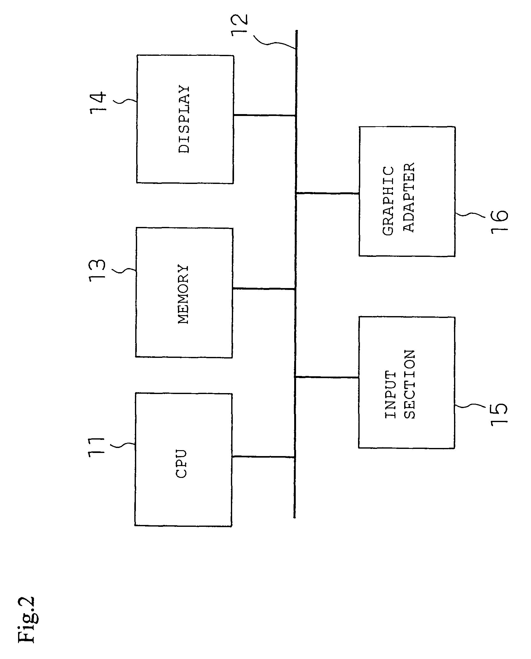
[0123]An image processing method according to a first embodiment according to the present invention will be explained. In this embodiment, images displayed on a screen of a personal computer (hereinbelow, referred to as PC) are intended to be consecutively loaded and compressed. FIG. 2 is a block diagram illustrating an image processing device of the present embodiment, while FIG. 3 schematically illustrates a PC screen.

[0124]In FIG. 2, a CPU 11 is connected to a bus line 12. A memory 13 and a display 14, as well as an input section 15 and a graphic adapter 16, are connected to the bus line 12 to constitute the image processing device.

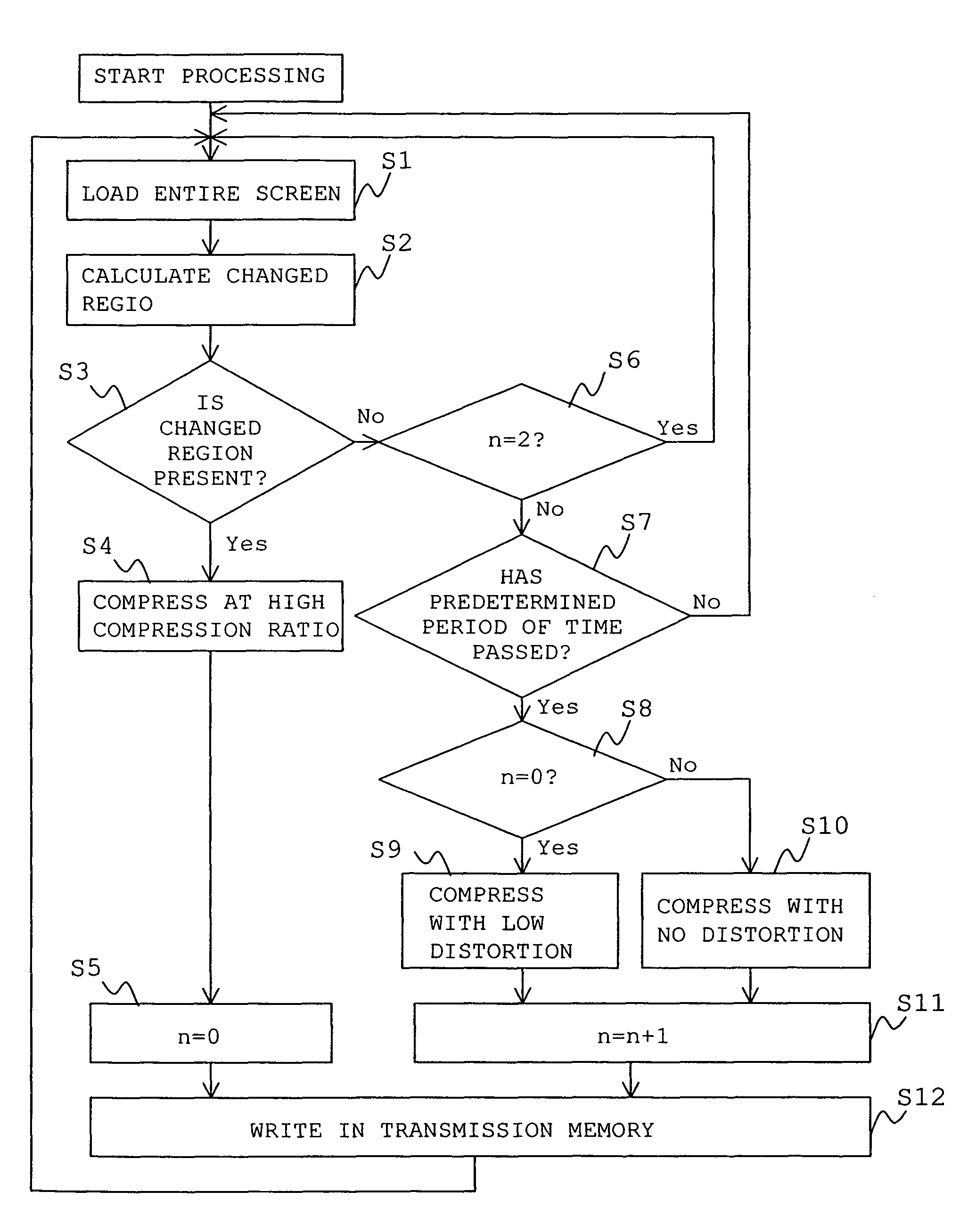
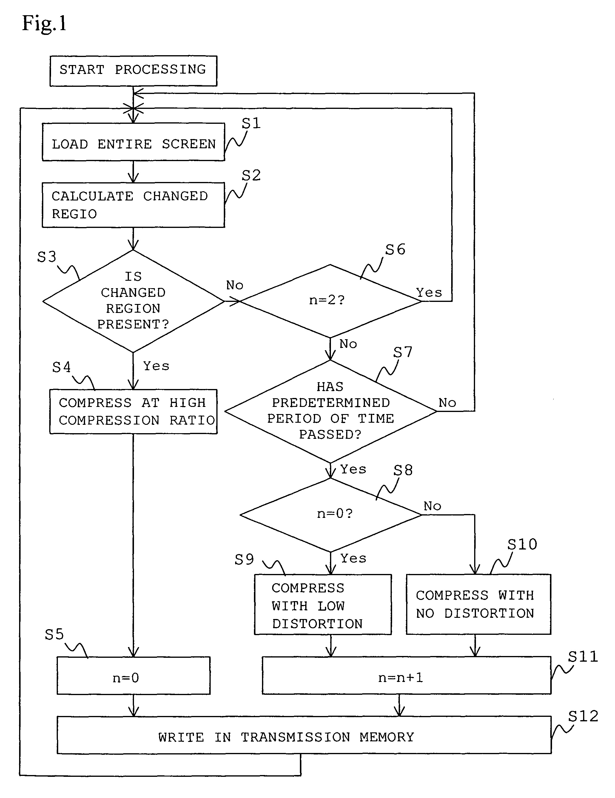
[0125]Next, an image processing method of the present embodiment will be explained in detail with reference to a flowchart shown in FIG. 1. At Step S1, contents of the whole PC screen are loaded into the memory in the PC. The contents of the whole PC screen are temporarily stored in an image memory (frame buffer or GRAM) and the image is periodically r...

second embodiment

[0153]An image processing method according to a second embodiment of the present invention will be explained. In this embodiment, the images displayed on the screen of the personal computer (hereinbelow, referred to as PC) is consecutively loaded and compressed. In other words, the contents of the whole PC screen are temporarily stored in the image memory (frame buffer or GRAM) and the image is periodically read therefrom to be compressed in the present embodiment. FIG. 6 illustrates the PC screen schematically, which shows an example in this embodiment to process the image by dividing it into four blocks of regions 26 to 29.

[0154]FIG. 5 is a flowchart illustrating the image processing method according to the second embodiment of the present invention. Hereinbelow, the method will be explained in detail with reference to FIG. 5.

[0155]At Step S21, the whole screen is captured. At Step S22, the image is divided into the blocks. In the example shown in FIG. 6, it is divided into the fo...

third embodiment

[0167]FIG. 7 is a block diagram of a display system according to a third embodiment of the present invention. In FIG. 7, reference numeral 31 represents a projector, reference numeral 32 represents a screen of the image from the projector to be projected, reference numeral 33 represents a PC, and reference numeral 34 represents a wireless LAN transceiver. In the display system, the image displayed on the PC 33 is loaded into the memory. The loaded image is then compressed and transmitted to the projector 31 via the wireless LAN transceiver 34. The projector 31 receives the compressed image and expands the image to be displayed on the screen 32. As a result, the image displayed on the screen of the PC 33 may be displayed on the screen 32 as well. It would be appreciated that the PC 33 is an image signal generating apparatus of generating an image signal, and the wireless LAN transceiver 34 constitutes a transmitting apparatus of transmitting the generated image signal. The projector ...


PUM


Abstract

In an image processing method of sequentially loading, compressing, and transmitting images to thereby display the images, there is provided the image processing method capable of preventing the images from degradation while keeping the responsibility until the image is displayed. When a changed region is determined to be present, the image is compressed using a method with a high compression ratio, while when there is no changed region and a predetermined period of time elapses, the image is determined to be static to thereby be compressed using a method with a low compression ratio and very little distortion.

Description

[0001]THIS APPLICATION IS A U.S. NATIONAL PHASE APPLICATION OF PCT INTERNATIONAL APPLICATION PCT / JP2004 / 003053.TECHNICAL FIELD[0002]The present invention relates to a transmitting apparatus, an image processing system, an image processing method, a program, and a storage medium of compressing an image generated by an image generating apparatus.BACKGROUND ART[0003]Conventionally, there have been proposed image processing methods of transmitting an image by dynamically changing a compressing method depending on image information or a condition of communication paths. The known methods include, for example, a method described in Japanese Unexamined Patent Publication (Kokai) No. H10-145796, pages 9 and 10 (first method). The entire disclosure of Japanese Unexamined Patent Publication (Kokai) No. H10-145796 is incorporated herein by reference in its entirety.[0004]First, the first method will be explained. FIG. 11 shows a coding apparatus 101 employing the first method. The coding appar...

Claims


Application Information

Patent Timeline
Patent Type & Authority Patents(United States)
IPC IPC(8): G06T9/00H04N7/12H04N7/26H04N7/30H04N7/50
CPCH04N19/172H04N19/115H04N19/137H04N19/127H04N19/61
Inventor MAEDA, TSUYOSHIWATANABE, TAKASHI
Owner PANASONIC CORP
Why Eureka
Try Eureka