
Laser system and method for non-destructive bond detection and evaluation

a laser system and non-destructive bond technology, applied in the direction of instruments, measuring devices, analysing solids using sonic/ultrasonic/infrasonic waves, etc., can solve the problems of large electron beam generator, defective bond area, and inability to observe weak bond areas with conventional ultrasound or thermal techniques, and achieve the effect of optimizing the acquisition of stress wave signature data

Active Publication Date: 2010-08-10
LSP TECH INC
View PDF24 Cites 38 Cited by
  • Summary
  • Abstract
  • Description
  • Claims
  • Application Information

AI Technical Summary

Benefits of technology

[0011]One advantage of the present invention is that a non-destructive evaluation and non-destruction inspection methodology has been developed.
[0012]Another advantage of the present invention is that the invention may employ a non-contact-type sensor to acquire the necessary stress wave signature data useful in identifying bond failure and bond condition.
[0013]A further advantage of the invention is that real-time evaluation of bond status and condition can be accomplished concurrently with collection of the stress wave signature data.
[0014]Another advantage of the invention is that the benefits of laser shock peening can be applied to the laser bond inspection process of the invention.
[0015]Another advantage of the invention is that a non-thermal loading mechanism can be employed to generate the shockwave activity needed to induce the stress waves in the article under study.
[0016]Another advantage of the invention is that various laser parameter values can be tailored to optimize acquisition of the stress wave signature data, such as pulse width, repetition rate, and energy level.

Problems solved by technology

These weak bond areas typically are not observable with conventional ultrasound or thermal techniques because the bond between layers, while weak, is intact or in contact and no delamination area exists that would be visible to standard inspection techniques.
These defective bonds could arise from improper preparation of the surfaces to be bonded, improper mixing, application, and / or curing of the adhesive, or contamination of the surfaces before bonding.
However, the electron beam generator is massive, therefore not portable, and the output beam cannot be conveniently moved around the surface of the aircraft to test the skin or other structural members.

Method used


Image

  • Laser system and method for non-destructive bond detection and evaluation
  • Laser system and method for non-destructive bond detection and evaluation
  • Laser system and method for non-destructive bond detection and evaluation

Examples


Embodiment Construction

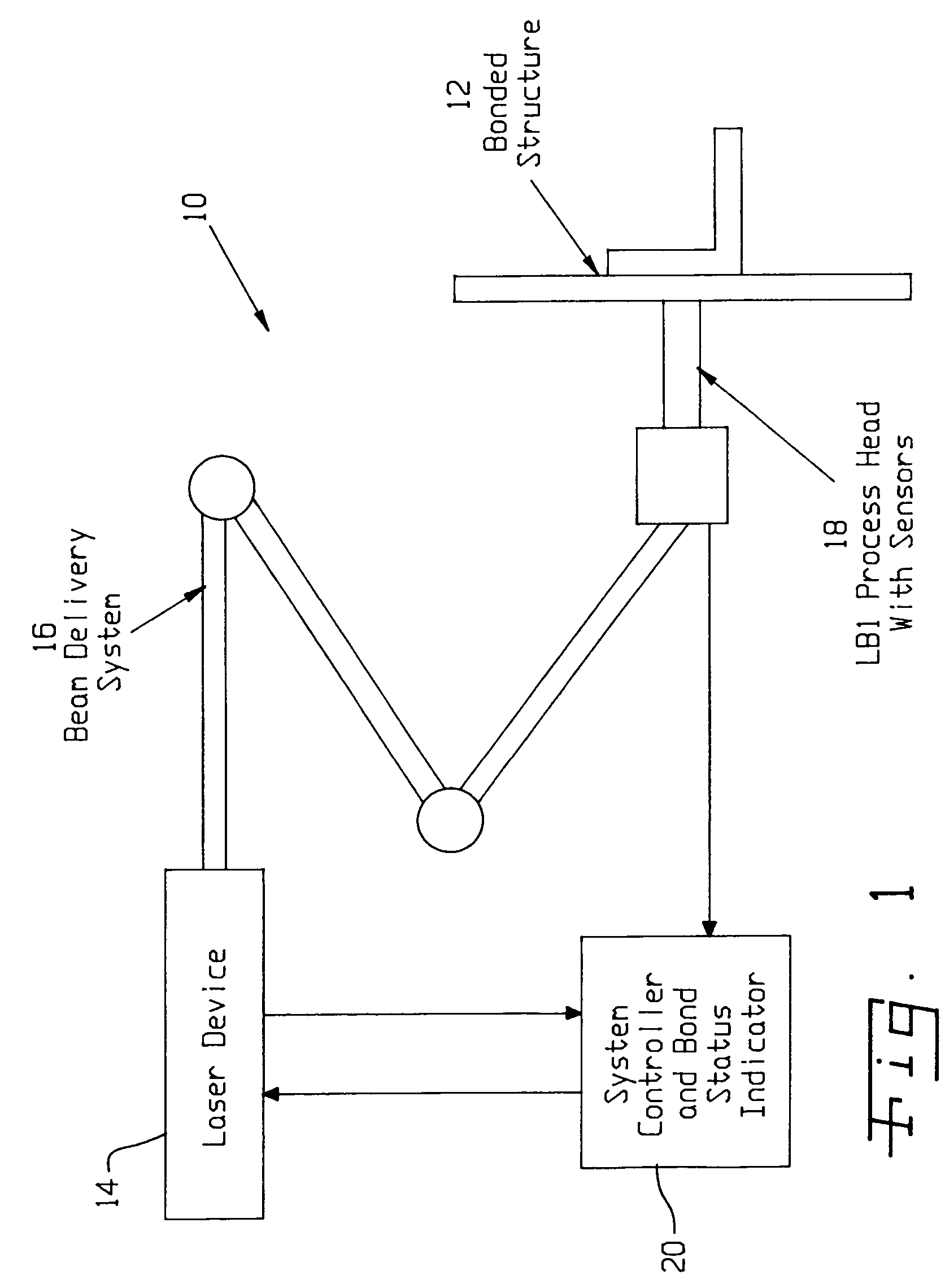
[0043]Referring now to the drawings and particularly to FIG. 1, there is shown a schematic block diagram illustration of a system 10 for evaluating the integrity of a bonded joint in a bonded structure or article 12, according to one form of the invention. As discussed further, system 10 includes a laser device 14 for emitting radiant energy; a beam delivery system (generally depicted at 16 in the exemplary form of an articulated arm assembly) for communicating the laser beam emissions to the target (i.e., article 12); a process head 18 providing an interface between the output of beam delivery system 16 and article 12, and further providing a sensor to collect measurement data from article 12; and a system manager provided in the form of processor-controller 20, which is configured to provide various control functions and to process and evaluate the data collected by the process head sensor, namely, stress wave signature data emanating from article 12.

[0044]The illustrated laser as...


PUM

PropertyMeasurementUnit
diameteraaaaaaaaaa
transit timeaaaaaaaaaa
thicknessaaaaaaaaaa

Abstract

A system for evaluating the integrity of a bonded joint in an article includes a laser configured in a laser shock processing arrangement to perform a laser shock processing treatment on the article. A beam delivery system employs an articulated arm assembly to communicate the radiant energy emitted by the laser to a process head proximate the article. The laser shock processing treatment causes the formation of shockwaves that propagate through the article, inducing internal stress wave activity that characteristically interacts with the bonded joint. A sensor detects a stress wave signature emanating from the article, which is indicative of the integrity of the bond. A detector such as a non-contact electromagnetic acoustic transducer provides a measure of the stress wave signature in the form of surface motion measurements.

Description

CROSS-REFERENCE TO RELATED APPLICATIONS[0001]This application claims the benefit of prior filed U.S. Provisional Application No. 60 / 507,076 entitled LASER SYSTEM AND METHOD FOR NON-DESTRUCTIVE BOND DETECTION AND EVALUATION filed Sep. 26, 2003, in the name of the above named inventors, the disclosure of which is incorporated herein by reference thereto.BACKGROUND OF THE INVENTION[0002]1. Field of the Invention[0003]The present invention relates to method and apparatus for preferentially testing the strength of composite bonds, and, more particularly, to the use of laser-induced shockwaves for conducting proof-testing of bonded joints in composite assemblies employing a non-destructive evaluation (NDE) and non-destructive inspection (NDI) strategy.[0004]2. Description of the Related Art[0005]An important task in the aircraft industry is the non-destructive inspection (NDI) of composite structures assembled with adhesive bonds. In particular, it is of interest to find weakly bonded lay...

Claims


Application Information

Patent Timeline
Patent Type & Authority Patents(United States)
IPC IPC(8): G01N29/04G01N29/24
CPCG01N29/2412G01N29/2418G01N2291/015G01N2291/0231G01N2291/0421G01N2291/2672
Inventor SOKOL, DAVID W.WALTERS, CRAIG T.DULANEY, JEFF L.TOLLER, STEVEN M.
Owner LSP TECH INC
Learn More