Control method and control unit for impact type screw fastening device

a control method and screw technology, applied in the direction of wrenches, drilling pipes, manufacturing tools, etc., can solve the problems of increased reaction force on the worker, large load on the worker, and inability to fasten a screw that requires high accuracy, etc., to achieve good accuracy

Active Publication Date: 2010-08-10
ESTIC CORP
View PDF17 Cites 877 Cited by
  • Summary
  • Abstract
  • Description
  • Claims
  • Application Information

AI Technical Summary

Benefits of technology

[0011]According to the conventional screw fastening device described above, current is supplied to the motor intermittently so that the motor generates pulse torque. Thus, good accuracy can be obtained despite a small reaction force that is exerted on the worker, and the worker can perform the screw fastening work by one hand.
[0012]However, the inventors have studied for improvement of accuracy of the tightening torque and reduction of time necessary for screw fastening in the screw fastening work so as to improve the screw fastening device described above.
[0013]Therefore, an object of the present invention is to improve accuracy of the tightening torque and reduce time necessary for screw fastening in the impact type screw fastening device having an electric motor as a rotation driving source.
[0016]In addition, when the torque reaches the first set value, a value of the current of every time of each pulse to be supplied to the motor may be decreased.

Problems solved by technology

A screw fastening device for one-hand requires the worker to receive reaction force of fastening a screw by one hand, so there is a problem of increase in the reaction force that is exerted on the worker as a load as the tightening torque increases.
A type of rotating the shaft continuously as described above puts a large load on the worker because the reaction force of the tightening torque is received directly by the worker's hand.
Therefore, it is not suitable for fastening a screw that requires high accuracy.
However, the oil pulse wrench has various problems as follows.
First, it is troublesome to adjust oil pressure of the bypass valve that works as the clutch mechanism.

Method used


Image

  • Control method and control unit for impact type screw fastening device
  • Control method and control unit for impact type screw fastening device
  • Control method and control unit for impact type screw fastening device

Examples


first embodiment

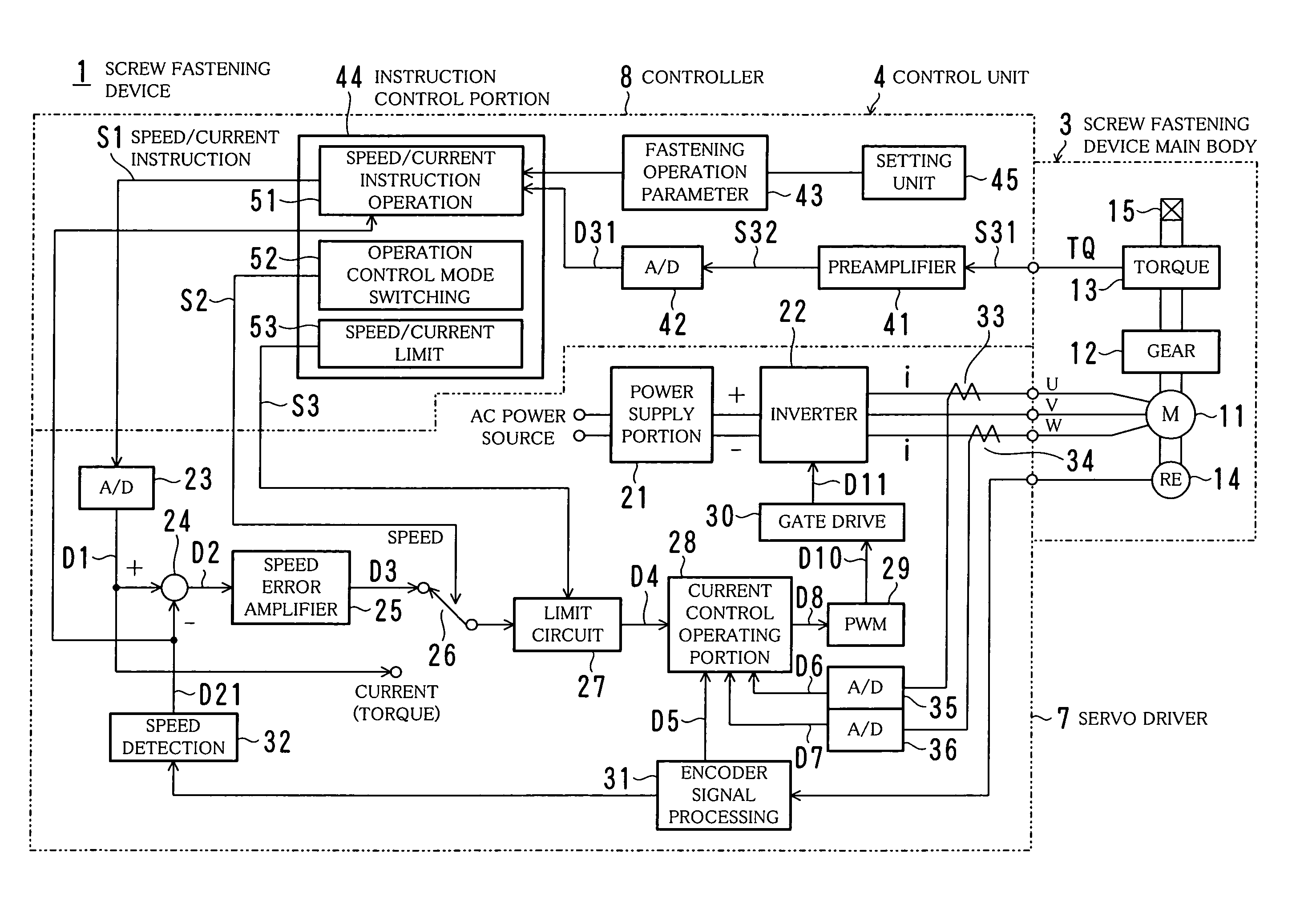
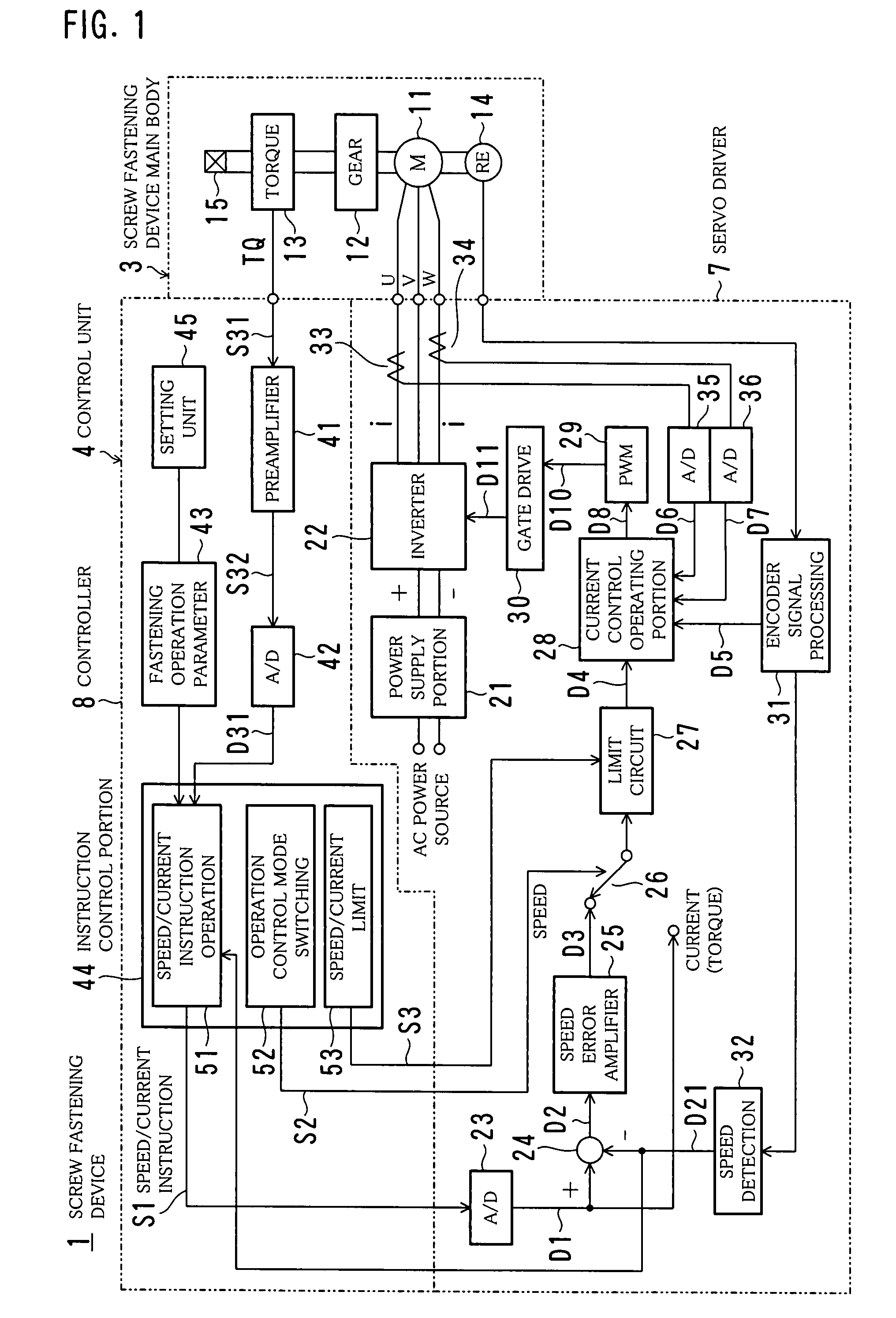
[0036]FIG. 1 is a block diagram showing a general structure of a screw fastening device 1 according to a first embodiment of the present invention.

[0037]In FIG. 1, the screw fastening device 1 includes a screw fastening device main body 3 and a control unit 4 having a servo driver 7 and a controller 8.

[0038]The screw fastening device main body 3 includes a motor 11, an impact generating unit 12, a torque sensor 13, an encoder 14, an output shaft 15, a casing (not shown), and a switch (not shown).

[0039]As the motor 11, a three-phase AC servo motor is used, for example. The impact generating unit 12 is an impact energy generating mechanism that converts rotation force of the motor 11 into intermittent impact force. Although various mechanisms can be used as the impact generating unit 12, a reduction gear including a planet gear and the like is used in the present embodiment. Backlash (play) of the planet gear and play of a joint portion or the like are used for generating impact. More...

second embodiment

[0115]Next, a second embodiment of the present invention will be described.

[0116]In the first embodiment described above, the increment ΔI2 of the current pulse DP in the second stage is set to a smaller value than the increment ΔI1 of the current pulse DP in the first stage. Thus, the increment ΔI2 of the current pulse DP is controlled so that the increment at every time of each pulse of the tightening torque TQ after the tightening torque TQ reaches the target approach torque TQN that is the first set value becomes smaller than that before reaching the target approach torque TQN.

[0117]In contrast, the second embodiment makes the current value of every time of each pulse that is supplied to the motor 11 small when the tightening torque TQ reaches the target approach torque TQN. Other functions and structures are the same in many parts as the first embodiment, so description of the same parts as the first embodiment is omitted or simplified, and only the points different from the fi...

third embodiment

[0127]Next, a third embodiment of the present invention will be described.

[0128]FIG. 13 is a flowchart showing a routine of the torque two-stage control process according to the third embodiment of the present invention.

[0129]In the third embodiment, the first embodiment and the second embodiment are combined. As shown in FIG. 13, in the first stage, the current value of the current pulse DP is set to D1T1 only the first time (#61). After that, if the tightening torque TQ has not reached the target approach torque TQN (No in #62), the increment ΔI1 is added to the current value (#63). After the tightening torque TQ reaches the target approach torque TQN (Yes in #62), the current value of the current pulse DP is set to D1T2 only the first time (#64). After that, the increment ΔI2 is added to the current value (#65). Note that the increment ΔI2 is a value smaller than the increment ΔI1.

[0130]More specifically, the third embodiment is a special case of the variation (3) of the second e...


PUM


Abstract

An object is to improve accuracy of tightening torque and to shorten time necessary for fastening a screw in an impact type screw fastening device that uses an electric motor as a rotation driving source. A control method for the impact type screw fastening device that uses an electric motor as a rotation driving source includes the steps of driving the motor to rotate by supplying current to the motor intermittently so that torque exerted on a load by rotation of the motor becomes like pulses on the time axis, and controlling the current of every time of each pulse so that an increment of every time of each pulse of the torque after the torque reaches a target approach torque TQN that is a first set value becomes smaller than that before it reaches the target approach torque TQN.

Description

TECHNICAL FIELD[0001]The present invention relates to a control method and a control unit for an impact type screw fastening device. In particular, the present invention relates to a screw fastening device with reduced reaction force so as to be adapted to one-hand use.BACKGROUND ART[0002]Conventionally, a power screw fastening device is used for fastening a bolt or a screw with predetermined torque. The screw fastening device rotates its shaft continuously so as to fasten a screw and usually performs controlling of turning off the power or disengage a clutch when the torque becomes a certain value.[0003]In various kinds of assembling lines, a worker often fastens a screw with respect to a work on a conveyor belt with a screw fastening device handled by hand.[0004]In this case, it is desirable that the screw fastening device can be operated by one hand from the viewpoint of workability. A screw fastening device for one-hand requires the worker to receive reaction force of fastening ...

Claims


Application Information

Patent Timeline
Patent Type & Authority Patents(United States)
IPC IPC(8): B25B21/02
CPCB23P19/066B25B23/1405B25B23/1475B25B21/00
Inventor ITO, TAKAYASHIBATA, YOSHITSUGUTAKAMURA, HITOSHI
Owner ESTIC CORP
Why Eureka
Try Eureka