Lens for concentrating low frequency ultrasonic energy

Inactive Publication Date: 2010-08-10
BACOUSTICS LLC
View PDF29 Cites 0 Cited by
  • Summary
  • Abstract
  • Description
  • Claims
  • Application Information

AI Technical Summary

Benefits of technology

[0010]The concentration of ultrasound energy above the surface of the lens may be magnified by refraction beneath the surface of the lens. When the lens contracts it induces an ultrasonic wave within the material of lens. The contours of the lens direct the compression about the wave towards the foci of the ellipses corresponding to each contour. The redirection of refraction compression can result in an increased deflection on regions of the lens located forty-five degrees above the foci of eac

Problems solved by technology

Concentrating acoustic energy carried by low frequency ultrasonic waves about a predetermined point by focusing such waves, however, is difficult endeavor.
The difficulty arises from the fact the low frequency ultrasound waves, unlike high intensity ultrasound waves, do not obey Snell's law of refraction.
Thus, when attempting to focus low frequency ultrasound waves Snell's law cannot be used to predict the location of the aggregat

Method used


Image

  • Lens for concentrating low frequency ultrasonic energy
  • Lens for concentrating low frequency ultrasonic energy
  • Lens for concentrating low frequency ultrasonic energy

Examples


Embodiment Construction

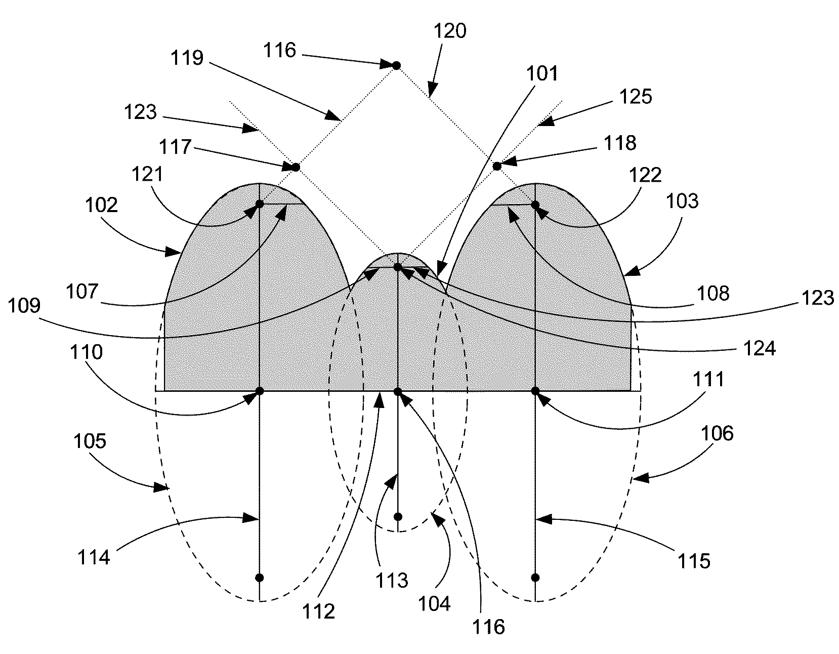
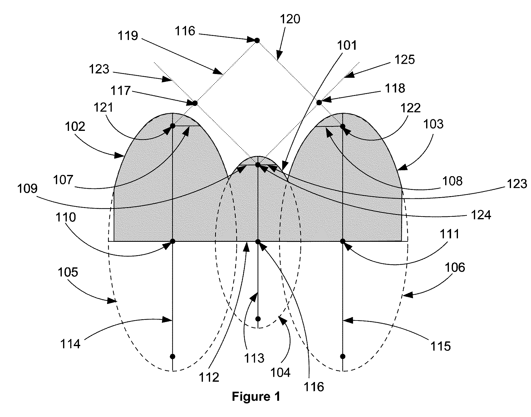
[0017]An ultrasonic lens configured according the present invention comprises at least three adjacent convex contours corresponding to the arcs of three ellipses each having a focus, a semi-latus rectum, a center, a major axis, and a minor axis. The contours are adjacent in that each contour shares a common vertex with at least one other contour. Any of the ellipses to which the three contours correspond may also have a second focus.

[0018]Depicted in FIG. 1 is a cross-section of one possible lens configured according to the present invention. As illustrated in FIG. 1, the first or center contour 101 shares a vertex with the second contour 102 and third contour 103. The first contour 101 corresponds to an arc of a first ellipse 104 in that contour 101 is a section of ellipse 104. The second contour 102 and third contour 103 are adjacent to and flank the first contour 101. The contours 102 and 103 correspond to arcs of two symmetrical ellipses, 105 and 106 respectively, having semi-la...


PUM


Abstract

Disclosed is an ultrasonic lens configuration permitting the production of an acoustic field from low frequency ultrasound waves with predictable regions of energy concentration. The lens comprises at least three adjacent convex surface contours. Each surface contour corresponds to an arc of an ellipse. The first surface contour is within the center of the lens and is flanked by two adjacent contours. The flanking contours correspond to arcs from two symmetrical ellipses having semi-latus rectums at least equal to the semi-latus rectum of the ellipse to which the first, central, contour corresponds. The contours of the lens are arranged such that the flanking contours extend past the first contour by positioning the contours so that if the ellipses to which they correspond were drawn the ellipses of the flanking contours directly adjacent to the first contour would have their centers aligned on a plane parallel to and not below the major or minor axis of the ellipse of the first contour.

Description

BACKGROUND OF THE INVENTION[0001]1. Field of the Invention[0002]The present invention relates to a lens for concentrating low frequency ultrasound with an acoustic field.[0003]2. Description of the Related Art[0004]As with light, it is possible to focus acoustics waves. Devices permitting a focusing of acoustic waves are generally referred to as lens. Acoustics lenses have been developed and utilized for a variety of purposes. Such lenses have been used to direct acoustics waves for the purpose of sonar detection. Acoustics lenses have also been employed to focus high frequency ultrasonic waves for the performance of various medical procedures such as sonograms. Less benign medical procedures can be performed using acoustics lenses to focus high intensity ultrasound on tissue to be ablated.SUMMARY OF THE INVENTION[0005]Disclosed is an ultrasonic lens configuration permitting the production of an acoustic field from low frequency ultrasound waves with predictable regions of energy co...

Claims


Application Information

Patent Timeline
IPC IPC(8): G10K11/00G02B15/14G01N29/04G02B21/18
CPCG10K11/30
Inventor BABAEV, EILAZ
Owner BACOUSTICS LLC
Why Eureka
Try Eureka