
Systems for preventing wear on turbine blade tip shrouds

a technology of tip shrouds and turbine blades, which is applied in the direction of liquid fuel engines, vessel construction, marine propulsion, etc., can solve the problems of extreme thermal stress on turbine blades and the tip shrouds attached thereto, extreme physical and mechanical stresses associated with the contact between adjacent tip shrouds, and extreme thermal stress on the tip shrouds, etc., to achieve durable outer surfaces and prevent wear.

Active Publication Date: 2010-08-10
GENERAL ELECTRIC CO
View PDF10 Cites 55 Cited by
  • Summary
  • Abstract
  • Description
  • Claims
  • Application Information

AI Technical Summary

Benefits of technology

The present patent describes a system for preventing wear on the tip shroud of a turbine blade in a turbine engine. The system includes a pocket in the contact surface of the tip shroud and a plug that fits snugly into the pocket. The plug has a durable outer surface, which may include a cobalt-based hardfacing powder. The pocket may be machined out of the contact surface, and the plug may be brazed or welded into the pocket. The system may also include a plate attached to the contact surface of the tip shroud, which also has a durable outer surface. The plate may cover the middle contact surface or have a lip that engages the edge of the contact surface. The system helps prevent wear and tear on the tip shroud during operation of the turbine.

Problems solved by technology

However, given the rotational velocity and vibration of the turbine in operation and the non-permanent nature of the joint made between adjacent tip shrouds, the physical and mechanical stresses associated with the contact between adjacent tip shrouds are extreme.
As a result, the thermal stresses on turbine blades and the tip shrouds attached thereto are extreme.
While these materials have proven cost-efficient and effective for most necessary functions, given the extreme mechanical and thermal stresses, the connective area between adjacent tip shrouds (i.e., where a tip shroud contacts each of the tip shrouds adjacent to it) tend to wear prematurely.
Conventional methods and systems have been unsuccessful at preventing this wear in an effective manner.
However, such coatings have proven to be too thin to provide any long-lasting protection.
However, specialized welding also has shown to provide little protection.
Further, weld build-up introduces further heat related stresses to the contact area, when operational stresses in this area already are extreme.
As a result, premature wear at the contact point between adjacent tip shrouds continues to result in system inefficiencies.
For example, premature wear may cause: 1) increased repair downtime to the turbine unit; 2) replacement of otherwise healthy tip shrouds due to the premature wear in the area of contact; and 3) related increases in labor and part expenses.

Method used


Image

  • Systems for preventing wear on turbine blade tip shrouds
  • Systems for preventing wear on turbine blade tip shrouds
  • Systems for preventing wear on turbine blade tip shrouds

Examples


Embodiment Construction

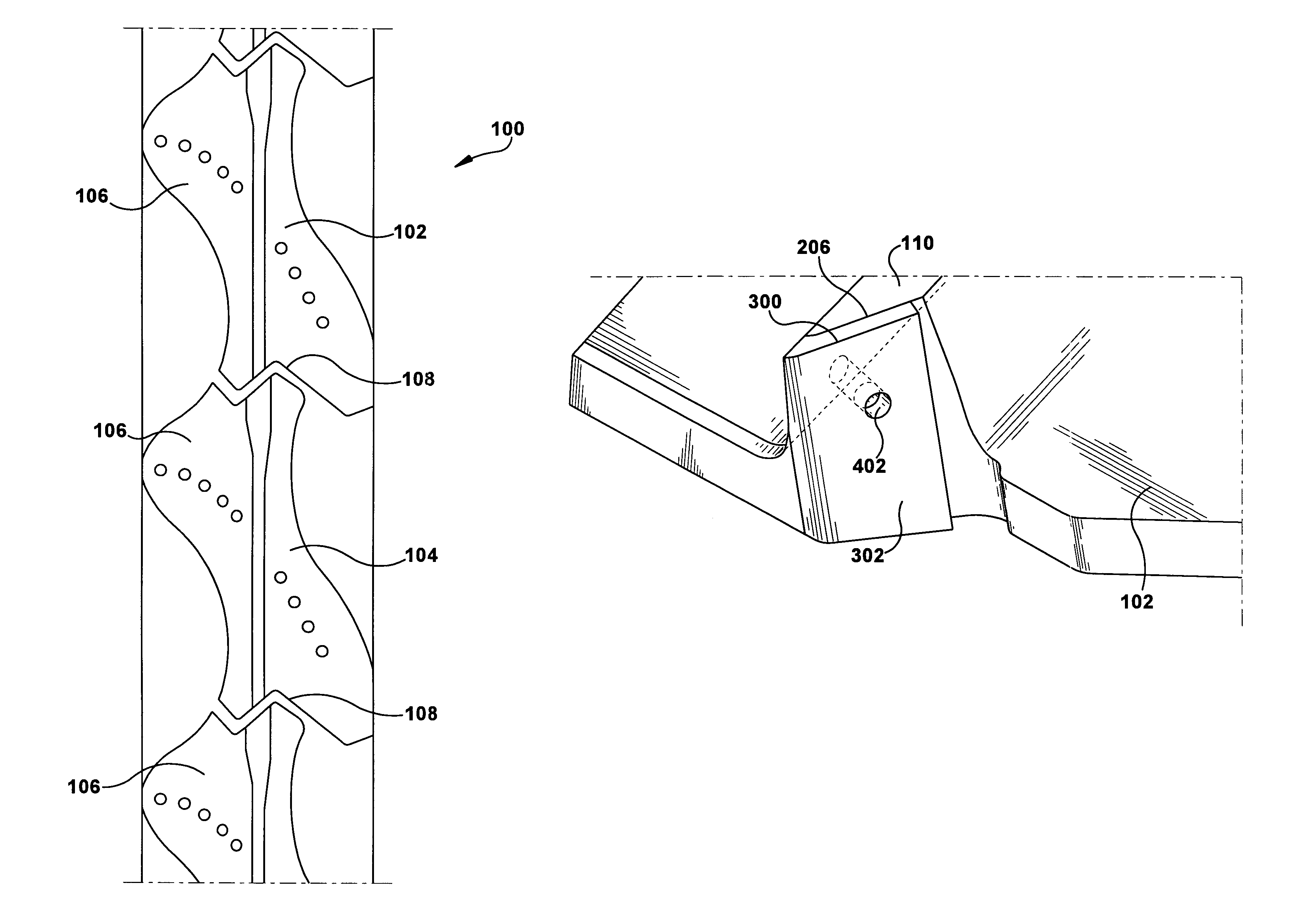
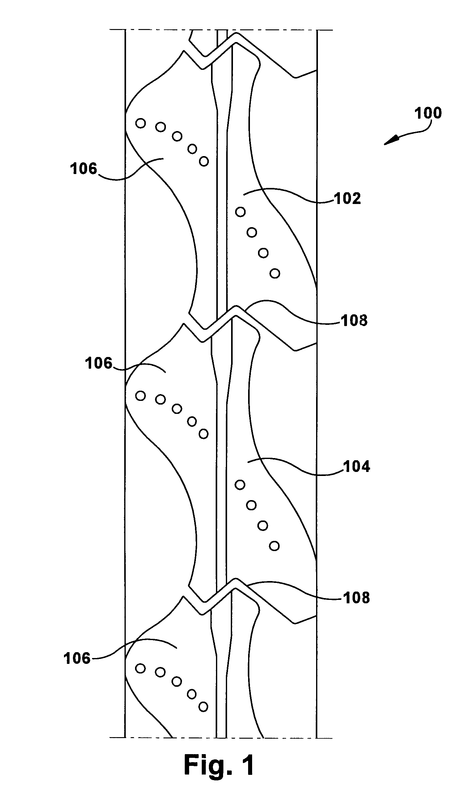
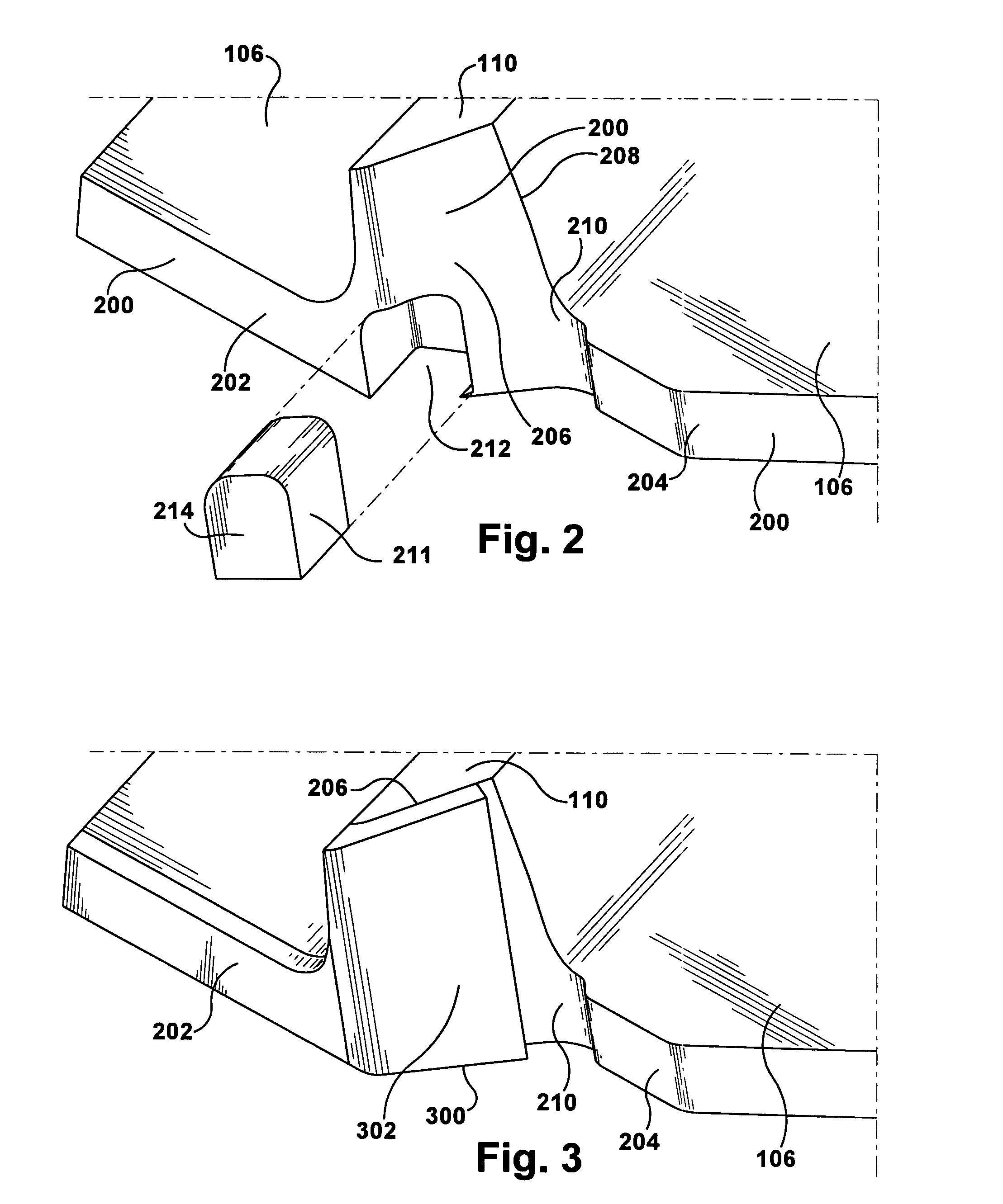
[0020]Referring now to the figures, where the various numbers represent like parts throughout the several views, FIG. 1 illustrates a top view of turbine blades 100 as assembled on a turbine rotor (not shown). A turbine blade 102 may be adjacent to a turbine blade 104. As visible from the top view, each turbine blade 100 may have a tip shroud 106. The leading edge of the tip shroud 106 of turbine blade 104 may contact or come in close proximity to the trailing edge of the tip shroud 106 of turbine blade 102. This area of contact may be referred to as a contact face or a Z-interface 108. As shown from the perspective of FIG. 1, the Z-interface 108 may from a rough “Z” profile between the two edges of the tip shrouds 106. Those of ordinary skill in the art will appreciate that the use of the turbine blade 100 and the tip shroud 106 are exemplary only and that other turbine blades and tip shrouds of different configurations may be used with alternative embodiments of the current applic...


PUM


Abstract

A system in a turbine engine for preventing wear on a tip shroud of a turbine blade that includes a pocket formed in a contact surface of the tip shroud and a plug that fits within the pocket and has a durable outer surface. The durable outer surface may include a cobalt-based hardfacing powder. The pocket may be machined out of the contact surface, and the plug may include a plug of predetermined size that fits snugly into the pocket. In some embodiments, the durable outer surface may substantially align with the contact surface after the plug is fitted into the pocket. In other embodiments, the durable outer surface may remain slightly raised from the contact surface after the plug has been fitted into the pocket.

Description

TECHNICAL FIELD[0001]This present application relates generally to systems for preventing wear on the tip shrouds of turbine blades in turbine engines. More specifically, but not by way of limitation, the present application relates to systems for integrating a durable outer surface onto the contact faces between adjacent tip shrouds.BACKGROUND OF THE INVENTION[0002]Turbine blades generally include an airfoil and a tip shroud attached thereto. The tip shroud, which attaches to the outer edge of the airfoil, provides a surface area that runs substantially perpendicular to the airfoil surface. The surface area of the tip shroud helps to hold the turbine exhaust gases on the airfoil (i.e., does not allow the exhaust gases to slide over the end of the airfoil blade) so that a greater percentage of energy from the turbine exhaust gases may be converted into mechanical energy by the turbine. Thusly, tip shrouds improve the performance of gas turbine engines. The preferred tip shroud desig...

Claims


Application Information

Patent Timeline
Patent Type & Authority Patents(United States)
IPC IPC(8): F01D5/22
CPCF01D5/225F05C2201/0463F05D2300/506
Inventor MOHR, PATRICKNOWAK, DANIELFERNANDEZ, EMILIOARNETT, MICHAELWILLIAMS, DAVIDCOLLADO, CARLOS
Owner GENERAL ELECTRIC CO
Learn More