Micropump and method for the production thereof

a micropump and valve seat technology, applied in the field of micropumps, can solve the problems of large position fluctuation of the gap on the membrane, high cost of micropump production, and easy misplacement of the gap on the valve seat, etc., and achieve the effect of reducing production costs

Inactive Publication Date: 2010-08-10
THINXXS MICROTECHNOLOGY AG
View PDF12 Cites 11 Cited by
  • Summary
  • Abstract
  • Description
  • Claims
  • Application Information

AI Technical Summary

Benefits of technology

[0010]The present invention has the object to create a new micropump of the afore-mentioned type which can be manufactured at lower costs compared to such known micropumps.

Problems solved by technology

By using relatively large valve membranes which are involved in forming both valves, the production of such micropumps is very costly.
It is particularly problematic to arrange the gaps in the membrane on the valve seats with the accuracy necessary for the functioning of the valves.
On the one hand, the distortion and shrinkage effects typical for plastic materials lead to big position fluctuations of the gaps on the membrane.
On the other hand, misplacements of the gaps on the valve seats can occur rather easily during the assembly of the thin and cumbersome membrane film.
The production yield under the conditions of serial production is thus very low.

Method used


Image

  • Micropump and method for the production thereof
  • Micropump and method for the production thereof
  • Micropump and method for the production thereof

Examples


Embodiment Construction

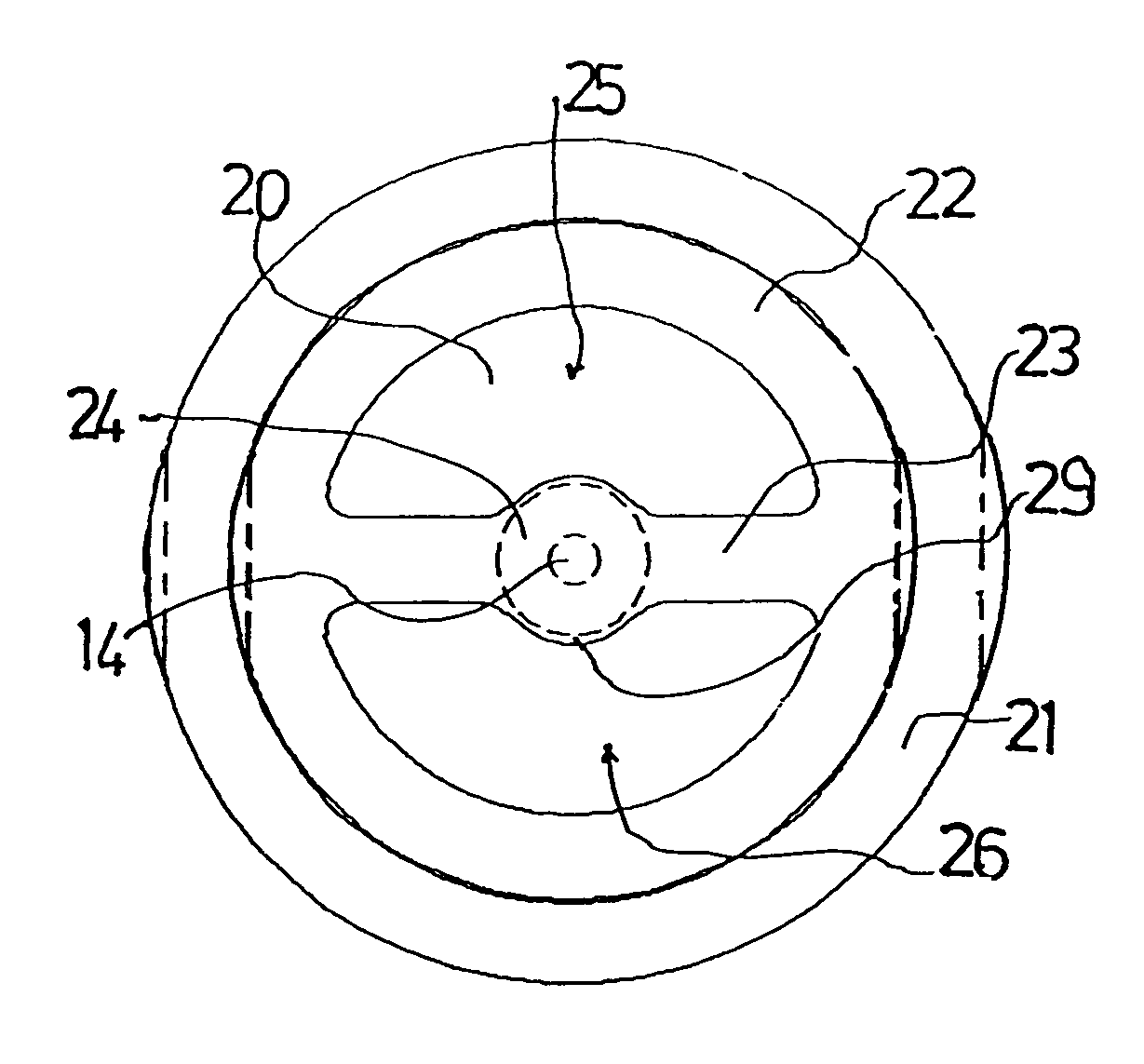
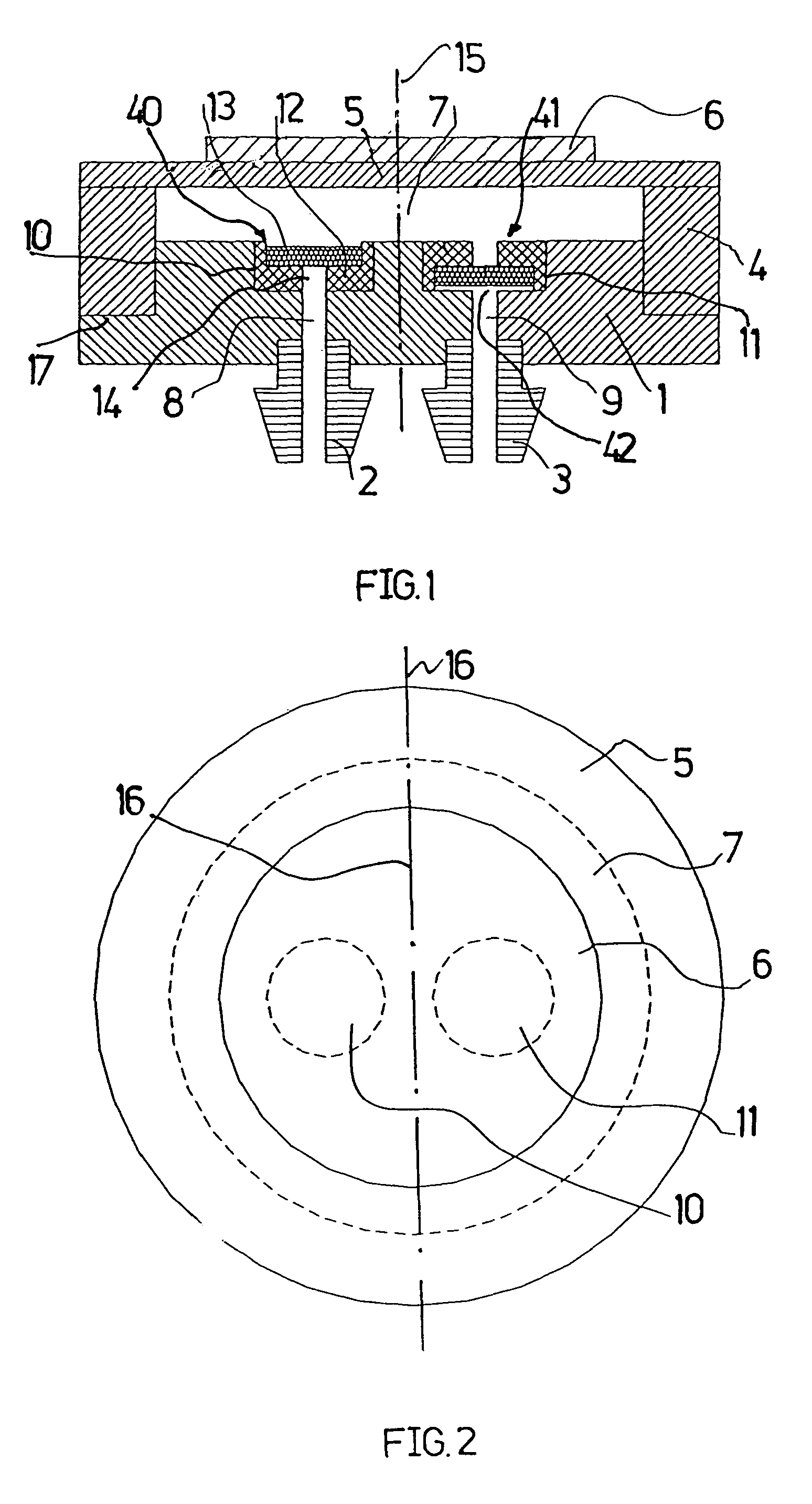
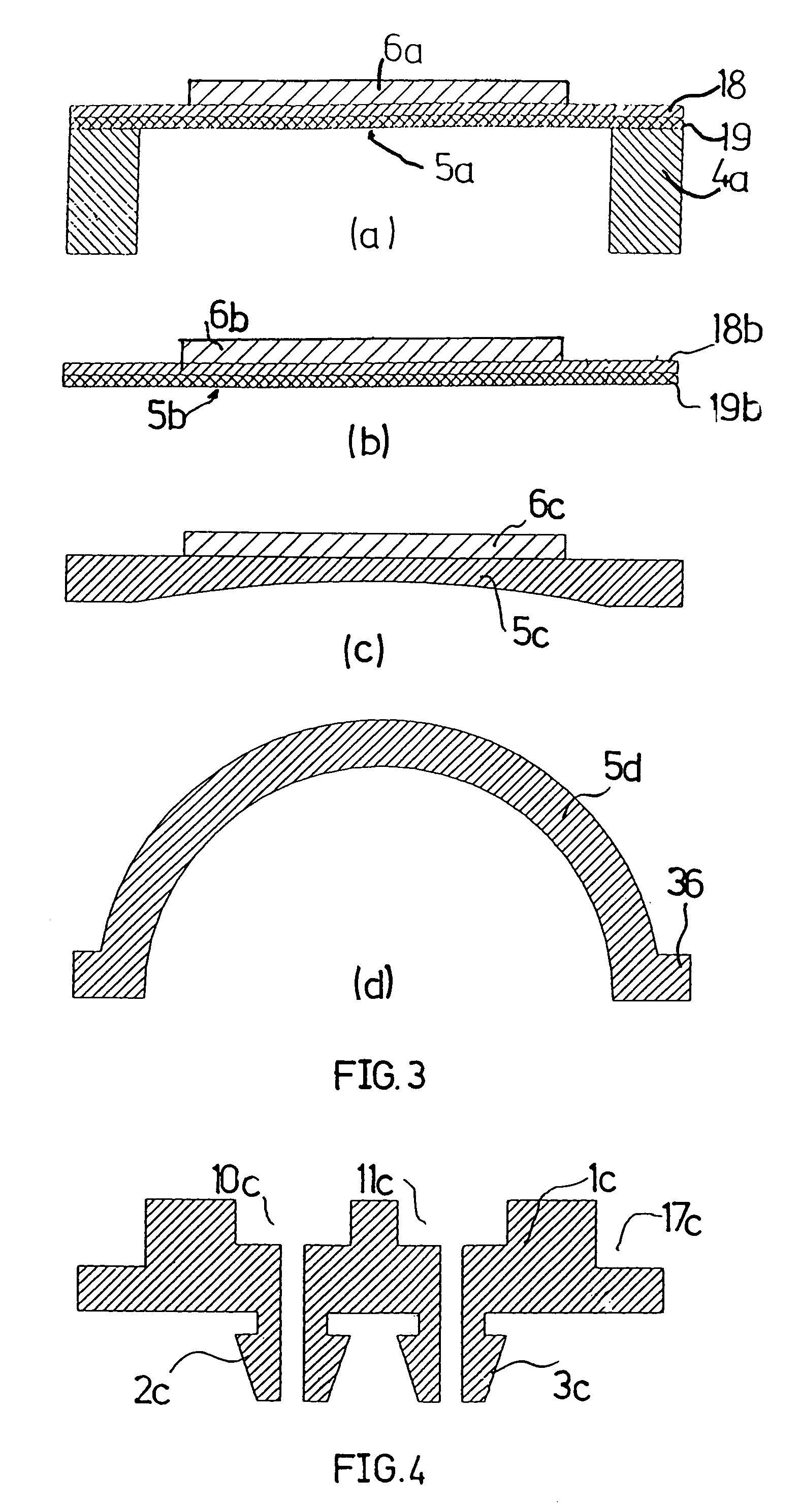
[0032]In FIG. 1 the reference numeral 1 designates a disk-shaped base part with a ring shoulder 17 at the circumference. The inlet connection 2 and the outlet connection 3 are attached to the base part 1. A membrane 5 connected with the ring support 4 at its outer edge by means of gluing or welding rests on the base part 1 over a ring support 4, the membrane itself being glued to a piezo disk 6. The ring support 4 could also be connected in one piece with the membrane 5.

[0033]A pump chamber 7 is formed between the membrane 5 and the base part 1 which is connected with the membrane by means of gluing or welding.

[0034]An inlet channel 8 is attached to the inlet connection 2 and an outlet channel 9 is attached to an outlet connection 3, wherein both channels each flow into a round cylindrical recess 10 or 11 in the base part 1. The channels 8 and 9 are arranged concentrically relative to the respective recess 10 and 11. Identically built valve modules 40 and 41 with a seat component 12...


PUM


Abstract

The invention relates to a micropump comprising a pump membrane (5) which can be moved by modifying the volume of a pump chamber which is adjacent to the pump membrane (5) and a base part (1), also comprising two valves which are arranged in recesses (10,11) in the base part and react to the pressure in the pump chamber in order to alternately open and close an inlet channel (8) and an outlet channel (9) for a medium to be pumped. According to the invention, the valves are formed by functioning valve modules (40,41) without any common components. The pre-manufactured valve modules, base modules comprising the base part and hose connections (2,3) and actuator modules comprising the actuator and the membrane are combined in order to produce said micropumps.

Description

BACKGROUND OF THE INVENTION[0001]1. Field of the Invention[0002]The invention relates to a micropump comprising a pump membrane which can be moved by modifying the volume of the pump chamber which is adjacent to the pump membrane and a base part, also comprising two valves which area arranged in recesses in the base part and react to the pressure in the pump chamber in order to alternately open and close an inlet channel and an outlet channel for a medium to be pumped.[0003]The invention further relates to a method for producing such a micropump.[0004]2. Description of the Related Art[0005]The lateral measurements of such micropumps which are fully or predominantly made of plastics are preferably between 5 and 30 mm for a height of 0.5 to 5 mm. The pump rates for fluids range between 10−5 and 0.2 l / min. The main fields of application include chemical and biochemical analytics, microreaction technology, the conveyance of gases, the conveyance and dosage of pharmaceutical agents, spec...

Claims


Application Information

Patent Timeline
Patent Type & Authority Patents(United States)
IPC IPC(8): F04B17/03F04B53/10F16K15/14F04B43/04
CPCF04B43/046F04B53/1062F16K15/144
Inventor WEBER, LUTZ
Owner THINXXS MICROTECHNOLOGY AG
Why Eureka
Try Eureka