Ablation catheter assembly with radially decreasing helix and method of use
Inactive Publication Date: 2010-08-10
MEDTRONIC INC
View PDF75 Cites 194 Cited by
Summary
Abstract
Description
Claims
Application Information
AI Technical Summary
This helps you quickly interpret patents by identifying the three key elements:
Problems solved by technology
Method used
Benefits of technology
[0016]Yet another aspect of the present invention relates to a method of electrically isolating a vessel from a chamber for treatment of cardiac arrhythmia. In this regard, the vessel forms an ostium at a wall of the chamber. With this in mind, the method includes selecting a catheter assembly including a catheter body and an ablative energy source. The catheter body includes a proximal portion and a distal portion, with the distal portion including an ablation section and a tip. The ablation section forms a loop and the tip extends distally from the ablation section. Further, the ablative energy source is associated with the ablation section. The distal portion of the c
Problems solved by technology
Disturbances in the heart's electrical system may lead to various rhythmic problems that can cause the heart to beat irregularly, too fast or too slow.
Patients experiencing atrial fibrillation may suffer from fatigue, activity intolerance, dizziness and even strokes.
While drugs may be the treatment of choice for some patients, drugs typically only mask the symptoms and do not cure the underlying cause.
Obviously, the prior catheter designs incorporating convoluted, multiple bends are not conducive to placement within a PV.
More particularly, due to the relatively small thickness of atrial tissue formed within a PV, it is likely that ablation of this tissue may in fact cause the PV to shrink or constrict.
Because PV's have a relatively small diameter, a stenosis may result.
These structures may be undesirably damaged when ablating within a PV.
Unfortuna
Method used
Image
Click on the blue label to locate the original text in one second.
Reading with bidirectional positioning of images and text.
Examples
Embodiment Construction
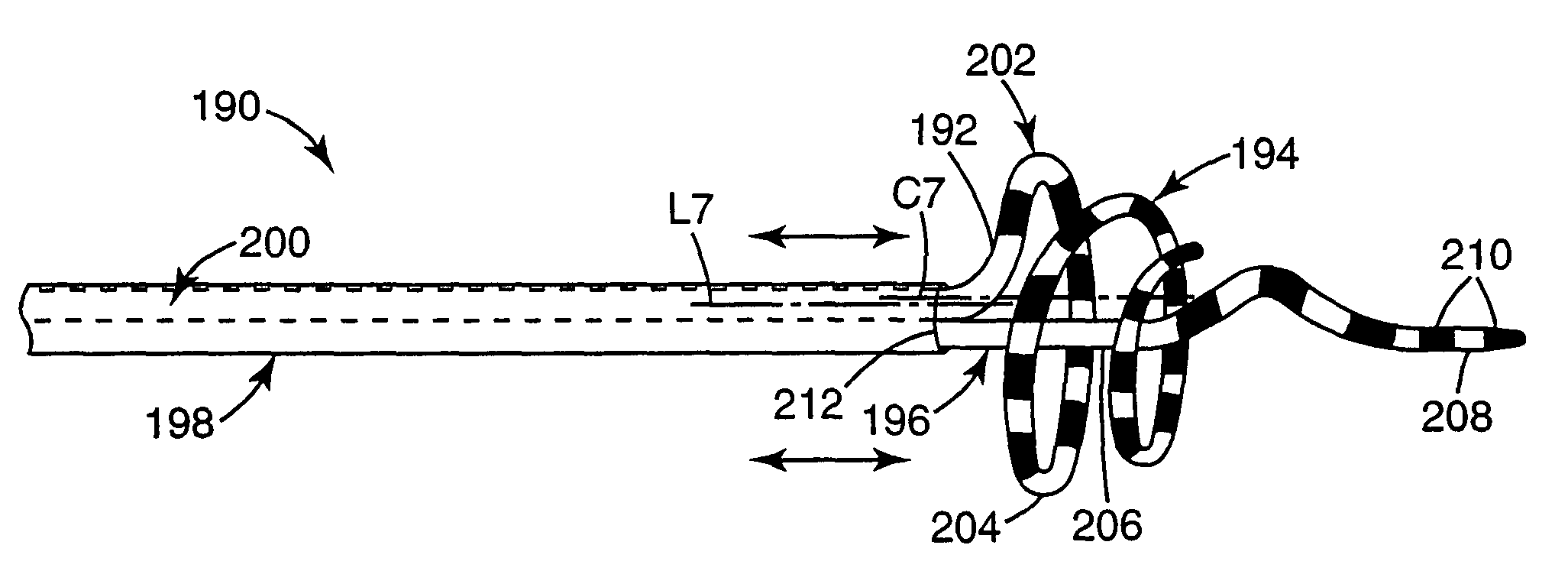
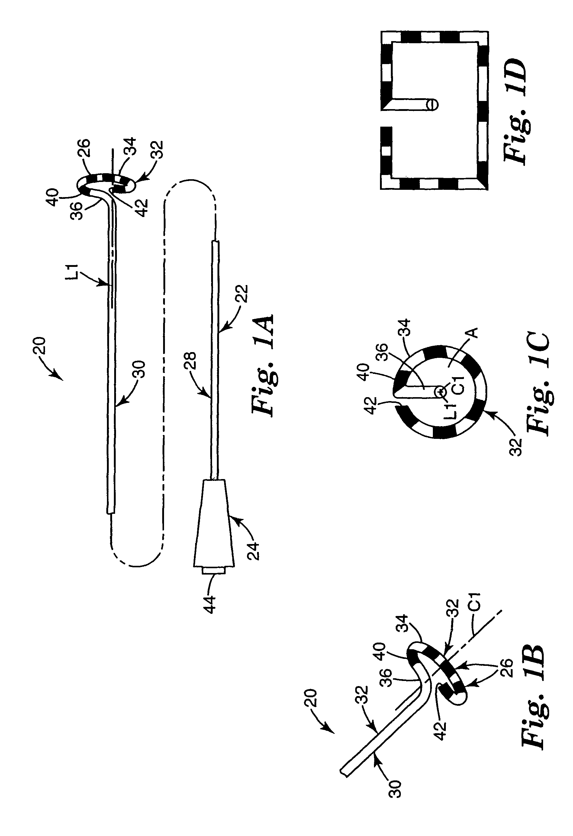
[0072]One preferred embodiment of a catheter assembly 20 in accordance with the present invention is shown in FIGS. 1A-1C. The catheter assembly 20 is comprised of a catheter body 22, a handle 24 and electrodes 26. As described in greater detail below, the catheter body 22 extends from the handle 24, and the electrodes 26 are disposed along a portion of the catheter body 22.
[0073]The catheter body 22 is defined by a proximal portion 28, an intermediate portion 30 and a distal portion 32, and includes a central lumen (not shown). Although not specifically shown, the catheter body may be configured for over-the-wire or rapid exchange applications. In one preferred embodiment, the proximal portion 28, the intermediate 30 and the distal portion 32 are integrally formed from a biocompatible material having requisite strength and flexibility for deployment within a heart. Appropriate materials are well known in the art and include polyamide.
[0074]The intermediate portion 30 extends from t...
PUM
Abstract
A catheter assembly for treatment of cardiac arrhythmia. The catheter assembly includes a catheter body and an ablative energy source. The catheter body includes a proximal portion, an intermediate portion, and a distal portion. The intermediate portion extends from the proximal portion and defines a longitudinal axis. The distal portion extends from the intermediate portion and includes an ablation section and a tip. The ablation section forms a loop defining a diameter greater than an outer dimension of a pulmonary vein ostium. The tip extends distally from the ablation section and is configured to locate a pulmonary vein. Finally, the ablative energy source is associated with the ablation section. With this configuration, upon activation of the energy source, the ablation section ablates a desired lesion pattern. In one preferred embodiment, the ablation section forms a distally decreasing radius helix, whereas the tip includes a relatively linear leader section. With this one preferred configuration, the tip readily locates a pulmonary vein and guides the ablation section to a seated relationship about a pulmonary vein ostium (or extra-ostial).
Description
CROSS-REFERENCE TO RELATED APPLICATIONS[0001]This application is a divisional of application Ser. No. 09 / 848,555, filed May 3, 2001, now U.S. Pat. No. 6,702,811, which is a continuation-in-part of Ser. No. 09 / 733,356, filed Dec. 8, 2000, now abandoned, which is a continuation-in-part of application Ser. No. 09 / 286,048, filed Apr. 5, 1999, now U.S. Pat. No. 6,325,797.BACKGROUND OF THE INVENTION[0002]The present invention relates to an ablation catheter for treatment of cardiac arrhythmia, for example atrial fibrillation. More particularly, it relates to an ablation catheter configured to electrically isolate portions or an entirety of a vessel, such as a pulmonary vein, from a chamber, such as the left atrium, with a lesion pattern and a method for forming such a lesion pattern.[0003]The heart includes a number of pathways that are responsible for the propagation of signals necessary to produce continuous, synchronized contractions. Each contraction cycle begins in the right atrium w...
Claims
Application Information
Patent Timeline
Application Date:The date an application was filed.
Publication Date:The date a patent or application was officially published.
First Publication Date:The earliest publication date of a patent with the same application number.
Issue Date:Publication date of the patent grant document.
PCT Entry Date:The Entry date of PCT National Phase.
Estimated Expiry Date:The statutory expiry date of a patent right according to the Patent Law, and it is the longest term of protection that the patent right can achieve without the termination of the patent right due to other reasons(Term extension factor has been taken into account ).
Invalid Date:Actual expiry date is based on effective date or publication date of legal transaction data of invalid patent.