Reactor heat transfer systems

Inactive Publication Date: 2010-08-10
ASHE ROBERT +1
View PDF11 Cites 6 Cited by
  • Summary
  • Abstract
  • Description
  • Claims
  • Application Information

AI Technical Summary

Benefits of technology

[0072]To satisfy condition c above, the heat exchanger is preferably immersed in the process fluid and should be fully insulated at all points other than where fully immersed in the process fluid. This ensures that all the heat gained or lost by the heat transfer fluid is transferred directly from and to the process fluid. This condition is most easily achieved by designing the heat exchanger as a coil or plate fully immersed in the process fluid.
[0073]It is further pref

Problems solved by technology

Many reactions are hazardous and care needs to be taken to ensure no accidents.
The design of reactors in common industrial use is however inherently unsuitable for measuring calorimetric data and thus the techniques described remain theoretical.
In some cases limited scope exists for increasing or decreasing the heat transfer area.
However, these features do not lend themselves to measuring the quantity of heat generated or liberated.
(the error on the installed device may be higher).
This would rise to 250% where the heat transfer fluid temperature changed by 0.1° C. This factor alone makes it virtually impossible to measure the heat of reaction in conventional reactors.
Furthermore, on a conventional reactor, heat leaking out of the system via the non-process side of the jacket can create serious error.
Furthermore, conventional ch

Method used


Image

  • Reactor heat transfer systems
  • Reactor heat transfer systems
  • Reactor heat transfer systems

Examples


example 1

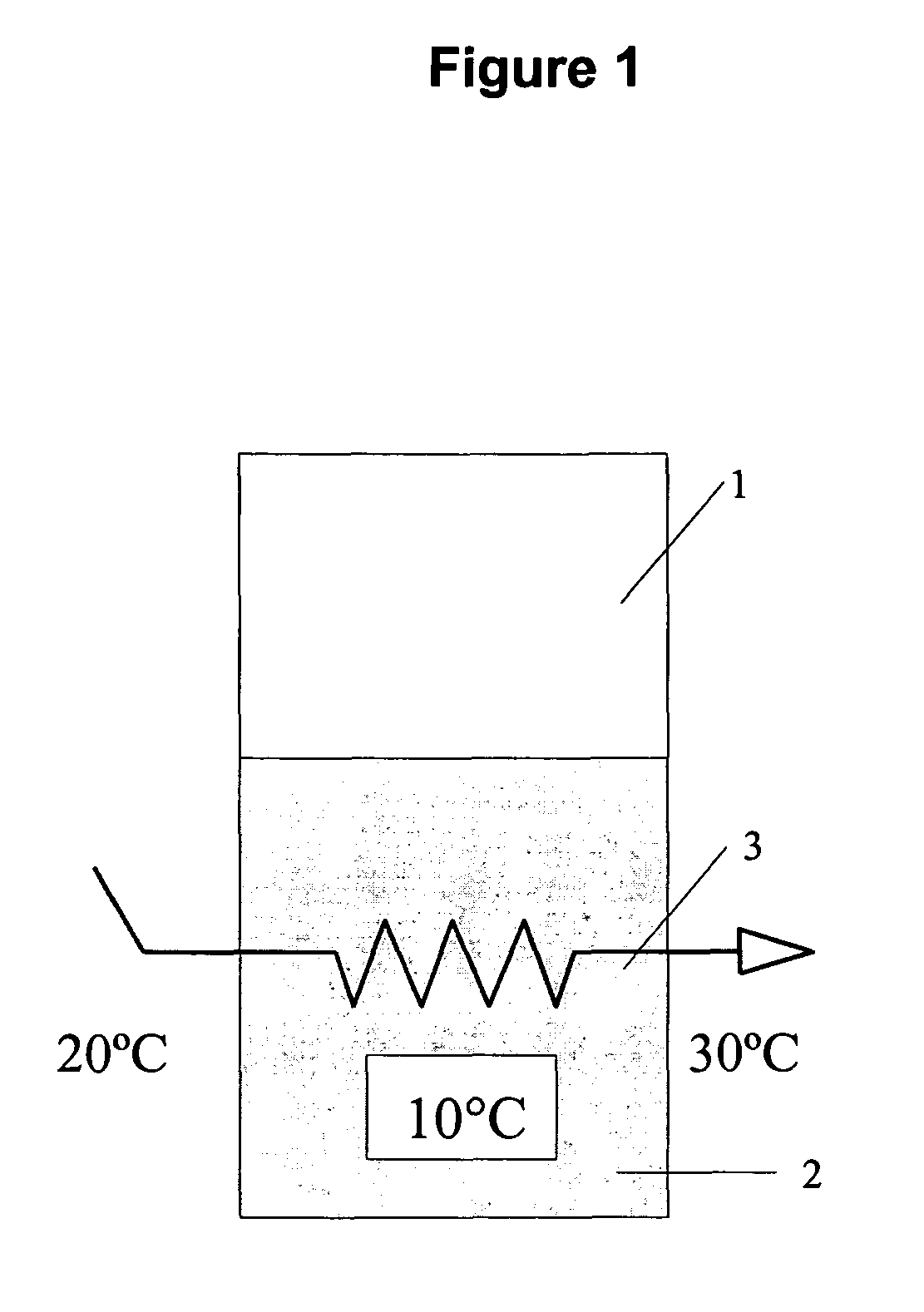
[0199]The heat transfer coil (3) serves two functions, it controls the process temperature and also measures the quantity of heat liberated (or absorbed); for the purpose of this example, the term tsi is used for the measured inlet temperature of the heat transfer fluid and tso for the outlet temperature of the heat transfer fluid. For effective operation, two factors need to be satisfied.[0200]i The temperature change in the heat transfer fluid (tsi−tso) must be sufficiently large to provide a good measurable difference. For this example a 10° C. temperature change of the heat transfer fluid (tsi−tso) has been selected.[0201]ii In general, the temperature difference between the heat transfer fluid and the process fluid must be as high as possible but not so great that boiling, burning or freezing occur on the pipe surface. Assume that the reaction temperature is 30° C. (tp). Also assume that the lowest temperature at which service fluid can be delivered to the system is 5° C. (to a...

example 2

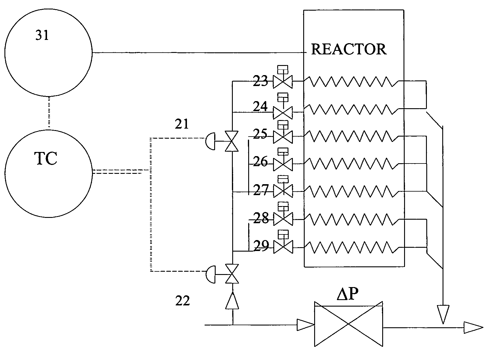
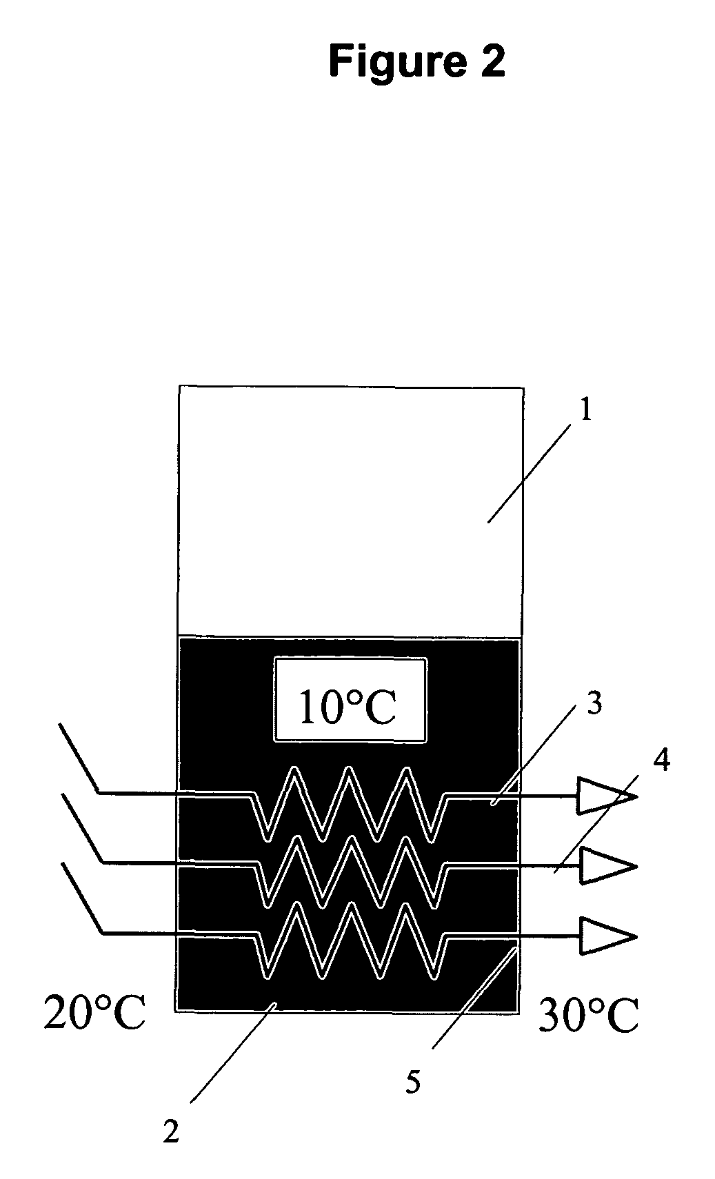
[0268]Example 2 illustrates, the design of variable area heat transfer systems employing multiple coil systems such as those illustrated in FIGS. 2 and 3. As in example 1, the cooling (or heating) coil system controls the process temperature and continuously measures the heat gained or lost using information on mass flowrate through the coil, temperature change (tsi−tso) and specific heat of the heat transfer fluid.

[0269]Example 2 addresses the fact that a reactor might be required to handle exothermic reactions which generate heat in the range of 500 to 15,000 W. A range of this size exceeds the operating capabilities of the single heat transfer coil system illustrated in example 1. Such a reactor can however be effectively operated using multiple coils as illustrated in this example (in this example identical coils each 11.8 m long are used) in a cascade fashion. With one coil operating with the heat transfer fluid at 1.7 m / s, a heat load of 457 W will give a temperature rise in s...

example 3

[0271]Table 4 sets out the heat transfer capacities of a series of coils of varying diameter and length.

[0272]

TABLE 4CoildiameterCoil length rangeOperating range(mm)(m)(W)10.13-0.6  4-2220.9-2.3 40-14131.9-4.7118-42943.0-7.8249-9135 4.4-11.8 457-1660

[0273]In order to arrive at the operating range, as with example 2, the LMTD is taken as 10° C. and (tsi−tso) as 10° C. The extremes of the ranges set out in columns two and three of table 4 represent the calculated values for minimum and maximum flow of the heat transfer fluid. Minimum flow is that which results in a pressure drop (of service fluid) of 0.1 bar·m−1 and maximum flow that which results in a pressure drop (of service fluid) 1 bar·m−1.

[0274]This combination of coil diameters and lengths provides a system capable of very high turndown rations. For example a six coil reactor can be designed to operate at less than 4 W and up to 5000 W. Table 5 shows the cumulative capacity of 6 coils of varying diameter.

[0275]

TABLE 5Cumulative...


PUM


Abstract

A reaction system in which a heat transfer fluid is carried through a process fluid in a conduit and the heat transfer surface area between the conduit and the process fluid can be varied according to the heat generated or absorbed by the reaction as determined by the temperature change in the heat transfer fluid across the reaction and the mass flow of the heat transfer fluid through the conduit.

Description

FIELD OF THE INVENTION[0001]The present invention relates to reaction systems and in particular reaction systems embodying improved heat transfer. Reaction systems may involve physical and / or chemical changes. Chemical reactions involve chemical change such as in the reaction of two or more molecules to produce a new molecule including polymerisation, in the breakdown of molecules into two or more molecules. Physical reactions involve a change of state such as in crystallisation, precipitation, evaporation, melting, solidification and the like. Certain reactions can involve both chemical and physical change.[0002]The invention is concerned with improving the ability to monitor the progress of physical and / or chemical reactions, it is also concerned with improving the control of reaction systems through the improved monitoring. The improved control that is provided by the present invention enables the production of materials of higher quality and purity, it enables more efficient use...

Claims


Application Information

Patent Timeline
IPC IPC(8): G05D23/00G05D7/00B01J19/00F28D21/00F28F27/02G01N25/42
CPCB01J19/0013F28F27/02G01N25/42B01J2219/0006B01J2219/00083B01J2219/0009B01J2219/00096B01J2219/0068
Inventor ASHE, ROBERTMORRIS, DAVID CHARLES
Owner ASHE ROBERT
Why Eureka
Try Eureka