Semiconductor heterostructure and method for forming same
a semiconductor heterostructure and heterostructure technology, applied in the direction of semiconductor devices, basic electric elements, electrical apparatus, etc., can solve the problems of not completely accepting the achieved surface properties of the semiconductor heterostructure when applying the above described prior art processes, rough surface is detrimental to the electrical behavior of the formed devices, and the surface roughness of the semiconductor heterostructure is not completely acceptable for further use. , to achieve the effect of reducing the surface roughness of the semiconductor heterostructure, improving the buried interface roughness, and reducing the surface rough
- Summary
- Abstract
- Description
- Claims
- Application Information
AI Technical Summary
Benefits of technology
Problems solved by technology
Method used
Image
Examples
first embodiment
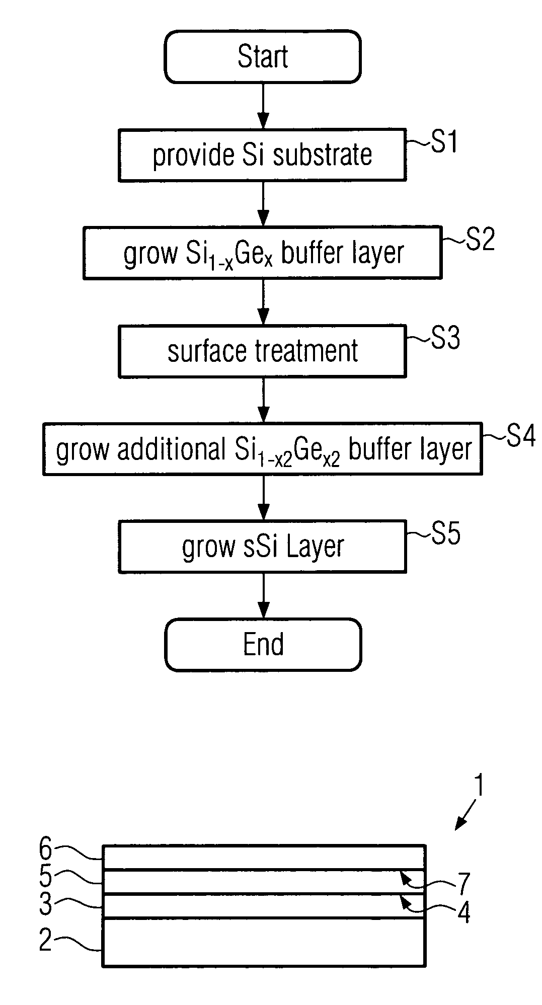
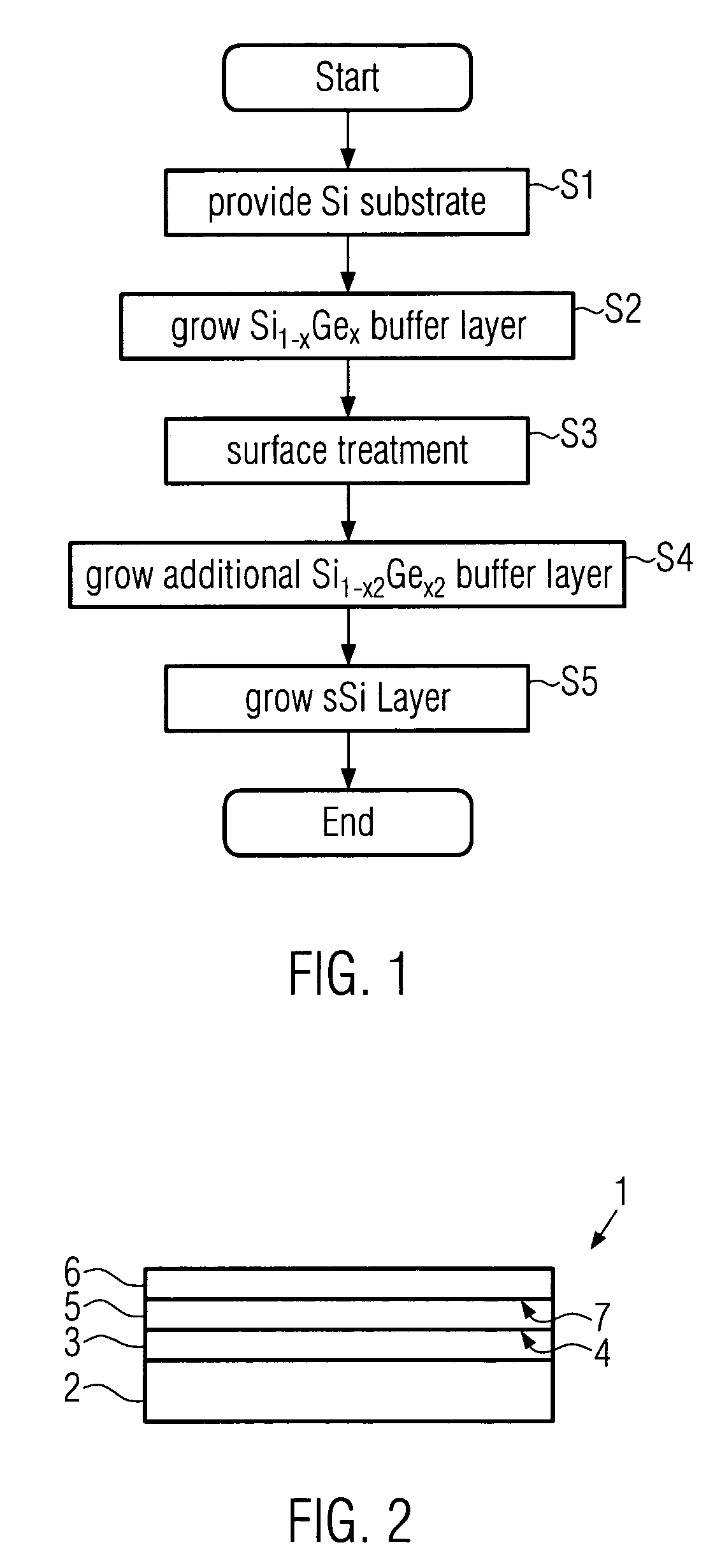
[0038]FIG. 1 is a block diagram illustrating the inventive method for forming a semiconductor heterostructure. In step S1 a silicon substrate is provided. Silicon substrates are readily available with different sizes and different crystalline surfaces. Then in step S2 a buffer layer of Si1-xGex is grown, preferably epitaxially, on the silicon substrate. The buffer layer can be a graded buffer layer, thus the concentration of the two compounds: silicon and germanium changes over the thickness of the buffer layer. By doing so the lattice parameter in the graded buffer slowly changes. For example, one can start with x=0 at the interface towards the silicon substrate, so that the lattice parameter corresponds to the one of the underlying Si substrate. Then the germanium concentration can grow until approximately 20%, thereby the in-plane lattice parameter becomes larger. It should be noted, however, that the final germanium concentration can be freely chosen, for instance 30% or 40%, an...
second embodiment
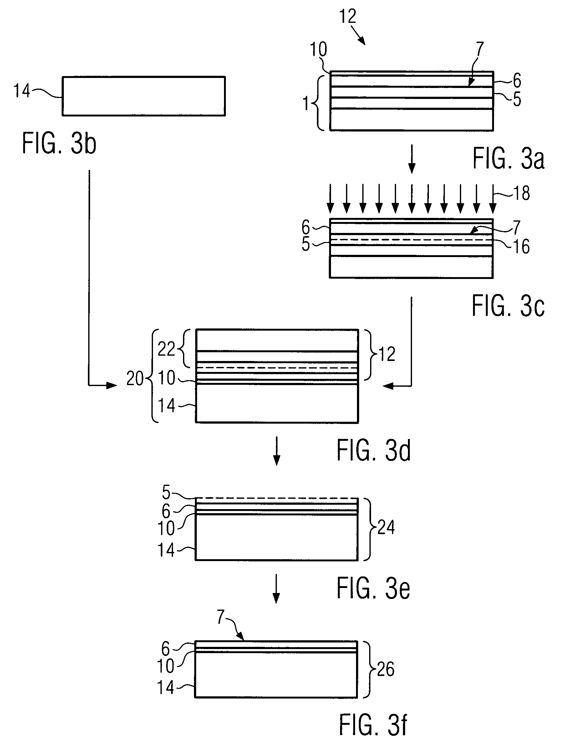
[0057]FIG. 3a illustrate the semiconductor heterostructure 1 comprising the strained silicon layer 6 and the additional layer 5, which has been fabricated according to the first or second embodiment described above. The semiconductor heterostructure is used as an initial donor substrate. On the stained layer 6 an isolating layer 10 is provided. This layer 10 is e.g., achieved by thermally oxidizing the strained layer 6. The heterostructure 1 together with the isolating layer 10 builds up a donor substrate 12.
[0058]FIG. 3b illustrates a handle substrate 14, typically a standard wafer, e.g., a Si wafer. The surface of the handle substrate can either be with or without the native or a grown isolating layer, e.g. the native SiO2 layer the case of a Si wafer.
[0059]FIG. 3c illustrates the process to create a predetermined splitting area 16 in the initial donor substrate 1. This is achieved by implanting atomic species 18, like for example hydrogen ions or other inert gases, with a predete...
PUM
 Abstract
Description
Claims
Application Information
 - R&D
- Intellectual Property
- Life Sciences
- Materials
- Tech Scout
- Unparalleled Data Quality
- Higher Quality Content
- 60% Fewer Hallucinations
Browse by: Latest US Patents, China's latest patents, Technical Efficacy Thesaurus, Application Domain, Technology Topic, Popular Technical Reports.
© 2025 PatSnap. All rights reserved.Legal|Privacy policy|Modern Slavery Act Transparency Statement|Sitemap|About US| Contact US: help@patsnap.com


