Power supply circuit

a power supply circuit and circuit technology, applied in the direction of instruments, amplifiers with semiconductor devices/discharge tubes, instruments, etc., can solve the problems of increasing the current of the output transistor, reducing the phase allowance, increasing the chip area, etc., to prevent the increase of the chip area and the current supplied

Active Publication Date: 2010-08-10
GK BRIDGE 1
View PDF10 Cites 2 Cited by
  • Summary
  • Abstract
  • Description
  • Claims
  • Application Information

AI Technical Summary

Benefits of technology

[0015]Therefore, a main object of the present invention is to provide a power supply circuit in which a shift of an output voltage of the power supply circuit is small, and a consumed current and a chip area are prevented from increasing as a power supply circuit installed in a device comprising a plurality of functions.

Problems solved by technology

In either case, such disadvantages are generated that the output voltage Vout of the power supply circuit is shifted, phase allowance is reduced, the current of the output transistor is increased, and additionally chip area is increased.

Method used


Image

  • Power supply circuit
  • Power supply circuit
  • Power supply circuit

Examples


embodiment 1

Preferred Embodiment 1

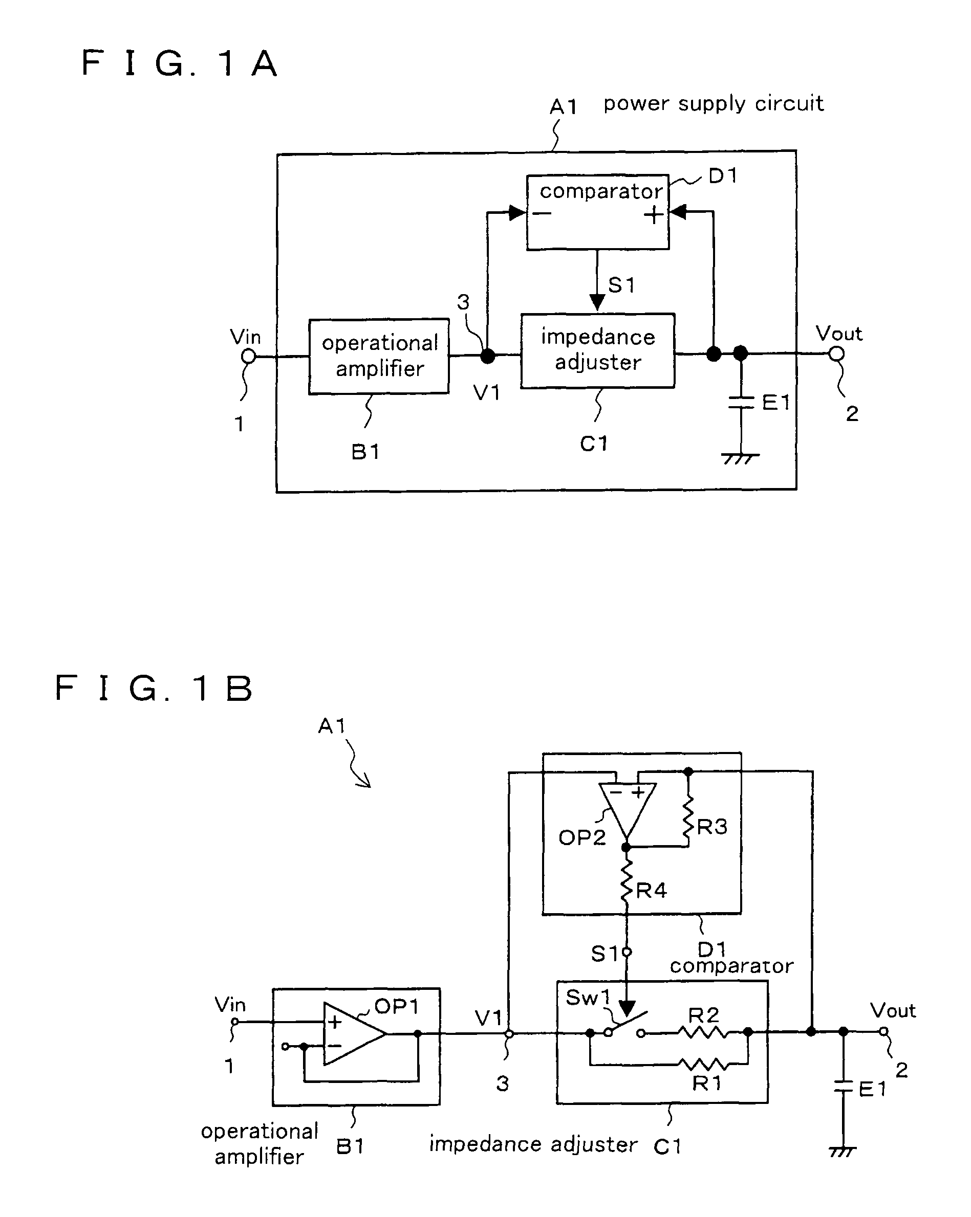
[0326]A power supply circuit according to a preferred embodiment 1 of the present invention is described below. FIG. 1A is a block diagram illustrating a constitution of the power supply circuit according to the preferred embodiment 1. FIG. 1B shows a detailed configuration of the circuit shown in FIG. 1A. Referring to reference symbols shown in FIGS. 1A and 1B, A1 denotes a power supply circuit, 1 denotes an input terminal of a reference potential Vin, 2 denotes an output terminal of the power supply circuit A1, B1 denotes an operational amplifier for generating a power supply potential V1 based on the applied reference potential Vin, C1 denotes an impedance adjuster inserted between an output terminal 3 of the operational amplifier B1 and the power supply circuit output terminal 2 and adjusting an impedance in accordance with a control signal S1, D1 denotes a comparator for comparing a power supply circuit output voltage Vout in the power supply circuit outpu...

embodiment 2

Preferred Embodiment 2

[0340]FIG. 11 is a block diagram illustrating a constitution of a power supply circuit A2 according to a preferred embodiment 2 of the present invention. In FIG. 11, the same references as those shown in FIG. 1 according to the preferred embodiment 1 denote the same constituent elements, and they are not described again. The power supply circuit A2 is provided with an operational amplifier B1′ to which a switchover phase compensator is attached in place of the operational amplifier B1. Accordingly, the impedance adjuster C1 and the operational amplifier B1′ are controlled by the control signal S1 from the comparator D1.

[0341]The operational amplifier B1′ is configured as shown in FIG. 12. A switchover phase compensator F1 is provided between the inversion input terminal (−) of the operational amplifier OP1 and an output terminal 3 of the operational amplifier B1′, and the two phase compensating circuits are selected by the switch. The operational amplifier OP1,...

embodiment 3

Preferred Embodiment 3

[0351]FIG. 16 is a block diagram illustrating a constitution of a power supply circuit A3 according to a preferred embodiment 3 of the present invention. In FIG. 11, the same references as those shown in FIG. 1 according to the preferred embodiment 1 denote the same constituent elements, and they are not described again. In the power supply circuit A3 according to the present preferred embodiment, the comparator D1 compares the power supply circuit output voltage Vout and the reference potential Vin applied to the input terminal 1 to each other, and outputs the control signal S1 in accordance with a result of the comparison to the impedance adjuster C1.

[0352]According to the present preferred embodiment, the input from the comparator D1 to the inversion input terminal (−) is free of any influence of the operational amplifier B1, which improves the response speed of the comparator D1. Any other operation is similar to that of the preferred embodiment 1 and is no...


PUM


Abstract

An operational amplifier generates a power supply potential from a reference potential. An impedance adjuster adjusts an output impedance of the operational amplifier in accordance with a control signal. A charge accumulator accumulates an output charge of the operational amplifier whose impedance is adjusted by the impedance adjuster. A comparator compares an output voltage of the operational amplifier before the impedance adjustment by the impedance adjuster and the output voltage of the operational amplifier after the impedance adjustment by the impedance adjuster to each other, and the comparator further generates the control signal in accordance with a result of the comparison so as to output the generated control signal to the impedance adjuster.

Description

BACKGROUND OF THE INVENTION[0001]1. Field of the Invention[0002]The present invention relates to a power supply circuit used in a liquid crystal display device or the like, more specifically to a power supply circuit with a high drive performance having mixed loading of a liquid crystal display drive, a control circuit, RAM and the like.[0003]2. Description of the Related Art[0004]In recent models of a mobile device typified by a mobile telephone and the like, types of the device, to which a power supply circuit for supplying power required for a plurality of functions is mounted, is increased. Such a model is advantageous in the point that power consumption and number of power-supply lines can be reduced by controlling on and off of the power supply in concert with on and off of the function.[0005]As this type of the power supply circuit, the power supply circuit has been conventionally known which could realize a phase stability of an output from an operational amplifier and respo...

Claims


Application Information

Patent Timeline
Patent Type & Authority Patents(United States)
IPC IPC(8): G05F1/00
CPCH03F1/56H03F3/45475H03F2203/45674G05F1/56H02M3/04
Inventor KOJIMA, TOMOKAZUHONDA, MINORU
Owner GK BRIDGE 1
Why Eureka
Try Eureka