Method of chemical protection of metal surface
a metal surface and chemical protection technology, applied in the direction of non-aqueous electrolyte cells, cell components, electrochemical generators, etc., can solve the problems of dendrite generation over repeat charge and discharge cycles, battery limitations, and drop in charge and discharge capacity
- Summary
- Abstract
- Description
- Claims
- Application Information
AI Technical Summary
Benefits of technology
Problems solved by technology
Method used
Image
Examples
example 1
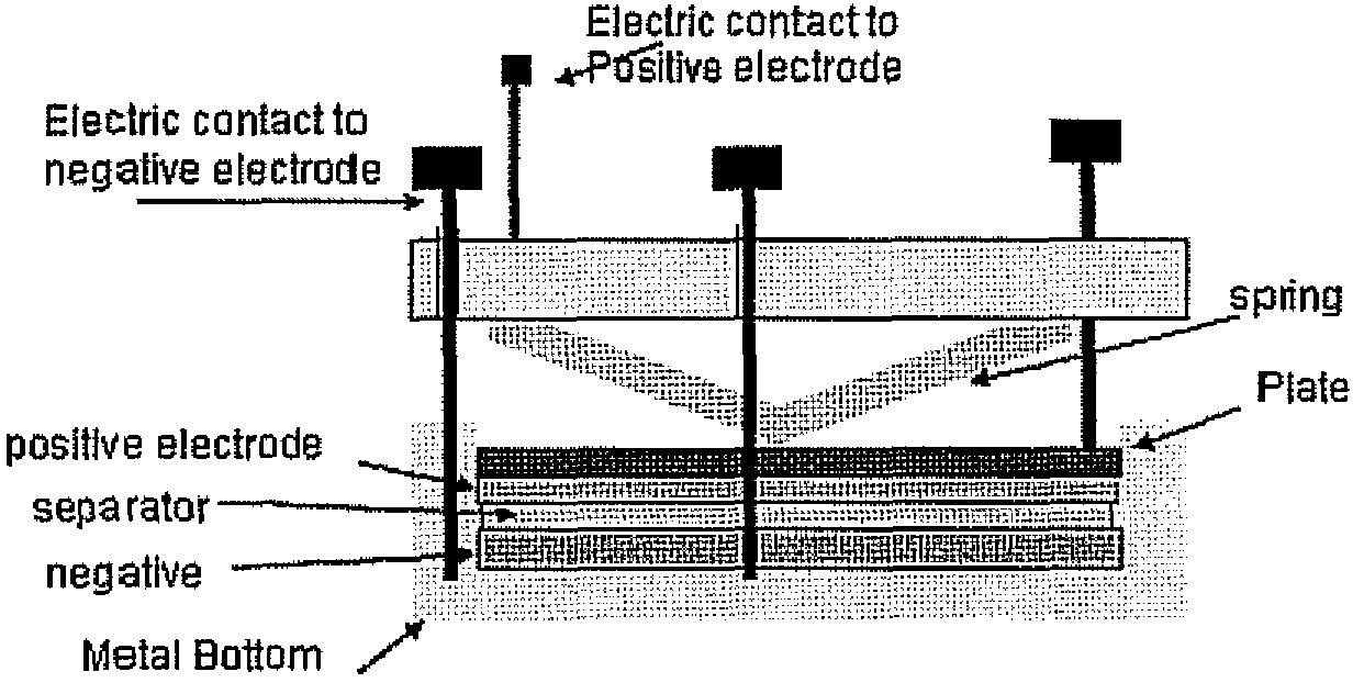
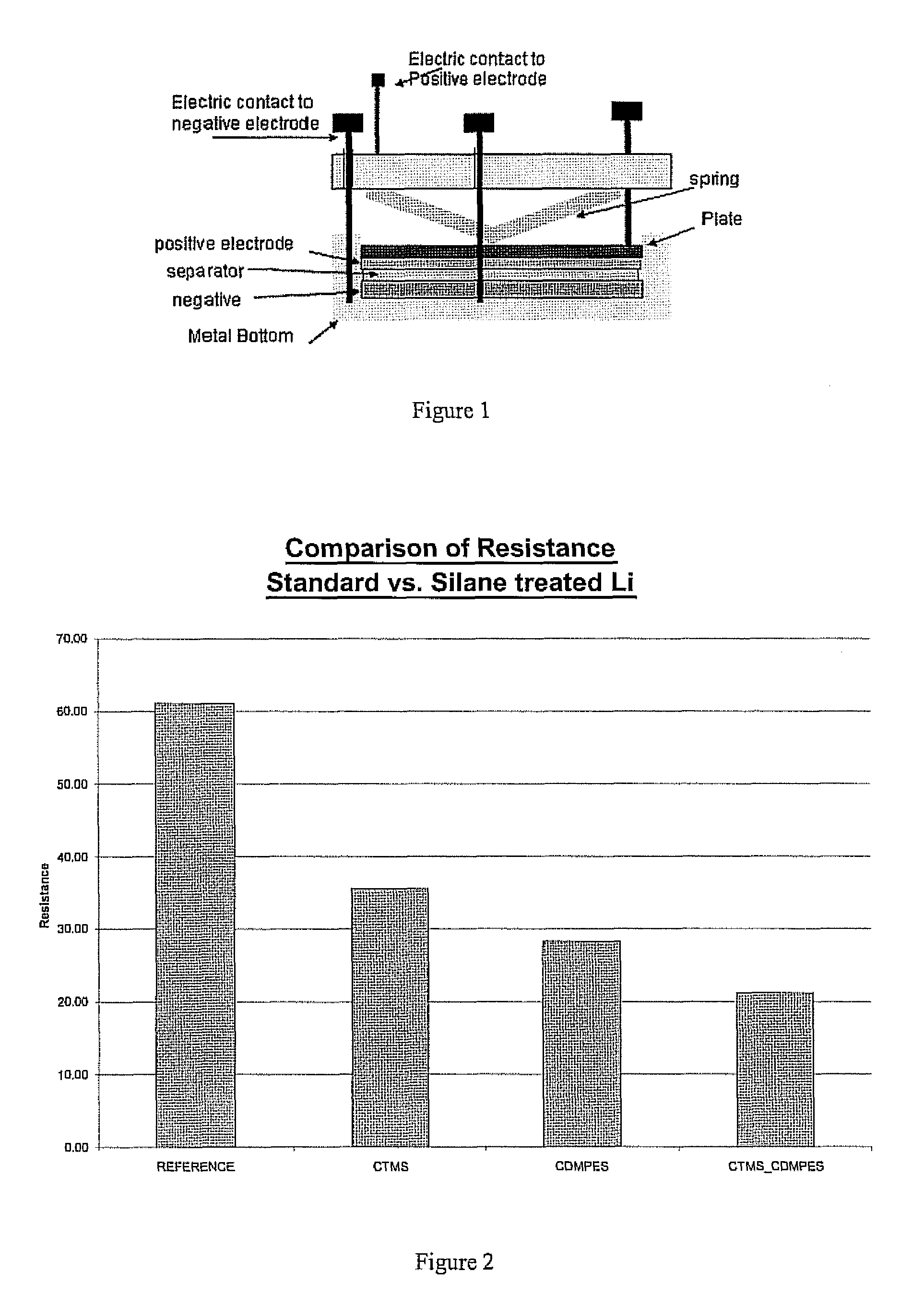
[0030]An untreated sample of the lithium metal and samples treated with chlorotrimethyl silane, chlorodimethylphenethyl silane and a sample treated with a first compound of chlorodimethylphenethyl silane followed by a second compound of chlorotrimethyl silane, according to the above procedure were analyzed using impedance testing to provide a resistance. Impedance tests were performed on the various treated samples of lithium and untreated lithium as a reference. The experimental setup used is shown in FIG. 1. The various samples were formed using the procedure described above. The lithium samples were tested in the experimental setup with the sample placed in the positive electrode position. The impedance values were used to calculate a resistance of the various samples, which are displayed in FIG. 2 for the various samples. As can be seen in FIG. 2, the resistance for all the treated samples is less than the untreated reference. However the lowest resistance is achieved with the s...
example 2
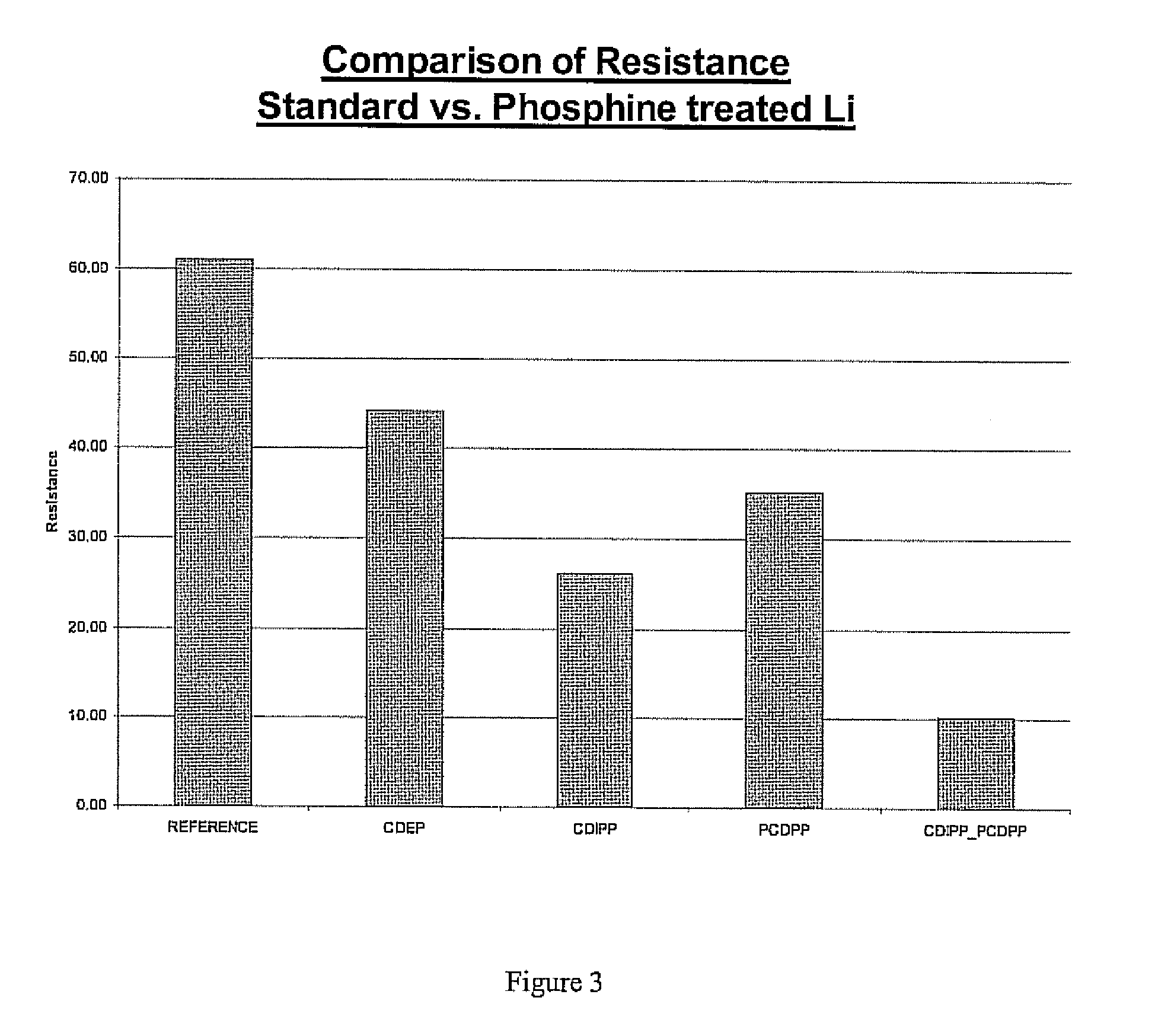
[0031]A similar experiment to that of example one was performed using first and second compounds having phosphorous based precursors including: chlorodiethylphosphine (CDEP), chlorodiisopropylphosphine (CDIPP), P-chlorodiphenylphosphine (PCDPP), and dimethylphosphinic chloride (DMPC). As with the previously described example, the samples were formed using the above described procedure and were subjected to impedance testing to generate resistance values displayed in FIG. 3. As with the previous examples all of the treated samples had a lower resistance than the reference. The lowest resistance was achieved in the sample prepared with a two step process of applying a first compound of PCDPP followed by a second compound of CDIPP. A graphical depiction of the sample prepared using The two step process is shown in FIG. 4. It can be seen that a surface coverage of the two compounds is greater than the molecularly large compound alone. The molecularly large PCDPP fills a portion of the s...
example 3
[0032]A similar experiment to that of the previous examples was performed using a first compound having a boron based precursor, including: bromodimethylborane (BDMB), and a second compound having D or P block based precursors including P-chlor diphenylphosphine (PCDPP). As with the previously described examples, the samples were formed using the above described procedure and were subjected to impedance testing to generate resistance values displayed in FIG. 5. As with the previous examples all of the treated samples had a lower resistance than the reference. The lowest resistance was achieved in the sample prepared with a two step process of applying a first compound of PCDPP followed by a second compound of BDMB.
[0033]Various combinations of the samples were prepared for the materials listed in Table 1 according to the above referenced procedures and testing protocols. The various resistances of the materials are displayed in FIG. 6. As can be seen from FIG. 6, all of the treated ...
PUM
| Property | Measurement | Unit |
|---|---|---|
| resistance | aaaaa | aaaaa |
| organo-metallic | aaaaa | aaaaa |
| inter-metallic | aaaaa | aaaaa |
Abstract
Description
Claims
Application Information
 - R&D
- Intellectual Property
- Life Sciences
- Materials
- Tech Scout
- Unparalleled Data Quality
- Higher Quality Content
- 60% Fewer Hallucinations
Browse by: Latest US Patents, China's latest patents, Technical Efficacy Thesaurus, Application Domain, Technology Topic, Popular Technical Reports.
© 2025 PatSnap. All rights reserved.Legal|Privacy policy|Modern Slavery Act Transparency Statement|Sitemap|About US| Contact US: help@patsnap.com


