Millimetre and sub-millimetre wave illumination system

Active Publication Date: 2010-08-17
QINETIQ LTD
View PDF13 Cites 3 Cited by
  • Summary
  • Abstract
  • Description
  • Claims
  • Application Information

AI Technical Summary

Benefits of technology

[0013]As the bandwidth is reduced the coherence of the radiation emitted from the exit apertures tends to increase, which in turn increases the amount of spatial variation in output power of the illuminator. Conversely, at larger bandwidths, the spatial variation in output power of the illuminator decreases. This can be understood by notionally regarding a wide bandwidth output as a set of different narrow bandwidth outputs. As the spatial variations at each bandwidth will be different, the integration of several such outputs tends to result in an averaging, or smoothing of the overall output from the illuminator.
[0014]At lower bandwidths, the applicant has realised that by generating a plurality of different radiation field states as defined herein within a pre-determined time interval the amount of spatial variation in output power seen by an associated imager is reduced. The plurality of different modes may be generated by disturbing the electromagnetic field pattern before the radiation has exited the exit apertures over a pre-determined time interval. If this is done, then the relative phases of the radiation emanating from the exit apertures will change and so the spatially noise-like radiation pattern from the illuminator will also change.

Problems solved by technology

For indoor use, this is more of a problem, as typically all elements within the scene will be at a similar temperature.
This can be detrimental to the overall image.

Method used


Image

  • Millimetre and sub-millimetre wave illumination system
  • Millimetre and sub-millimetre wave illumination system
  • Millimetre and sub-millimetre wave illumination system

Examples


first embodiment

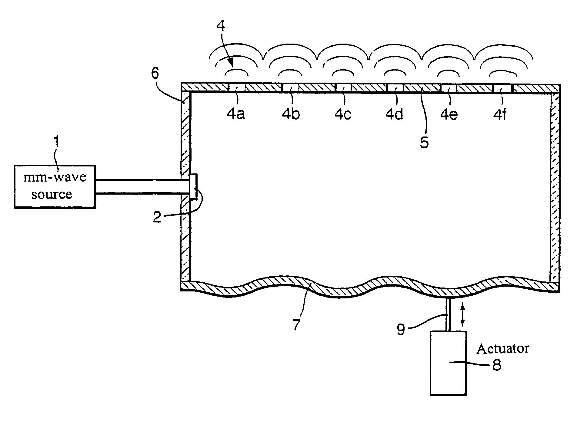
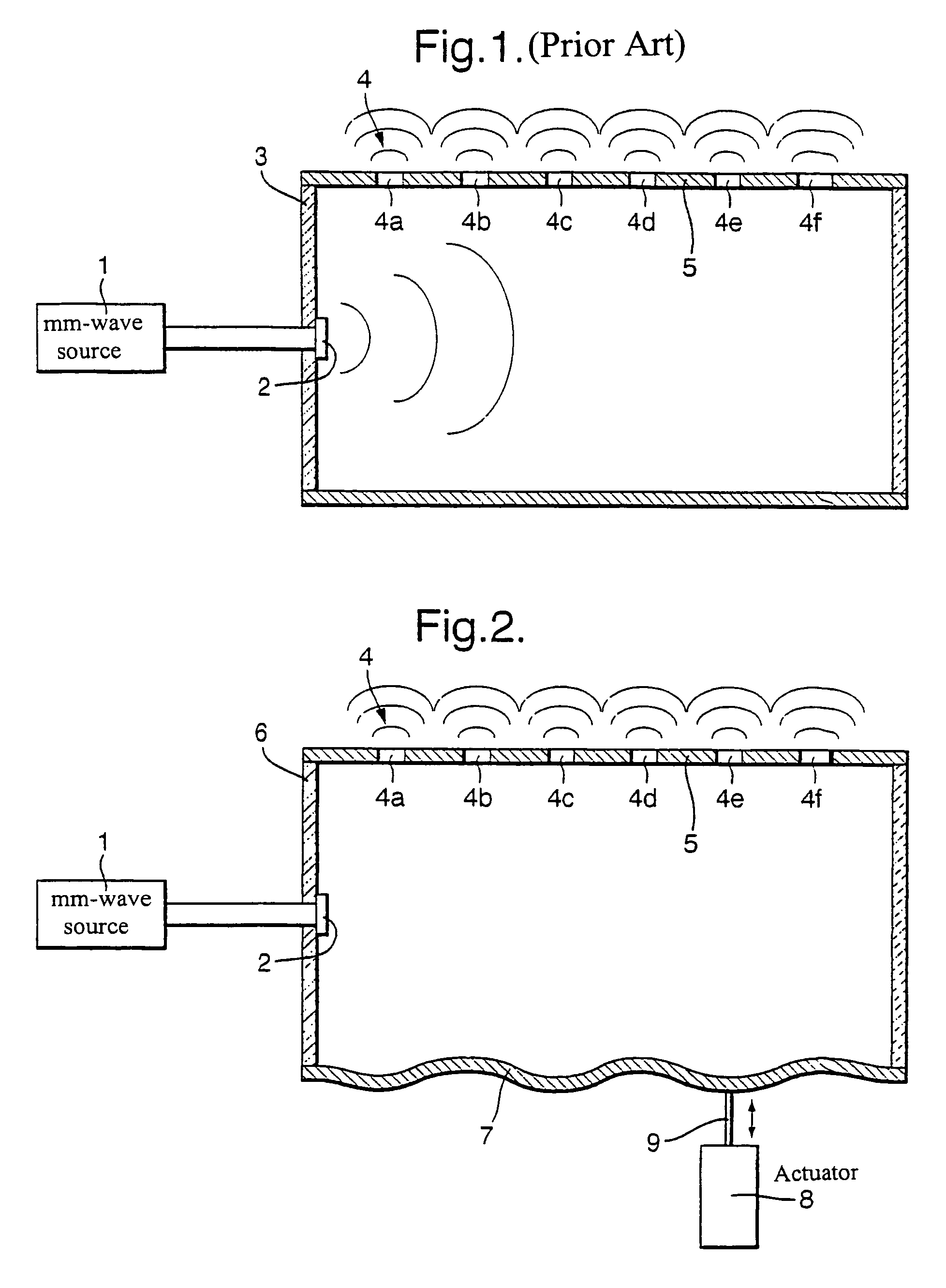
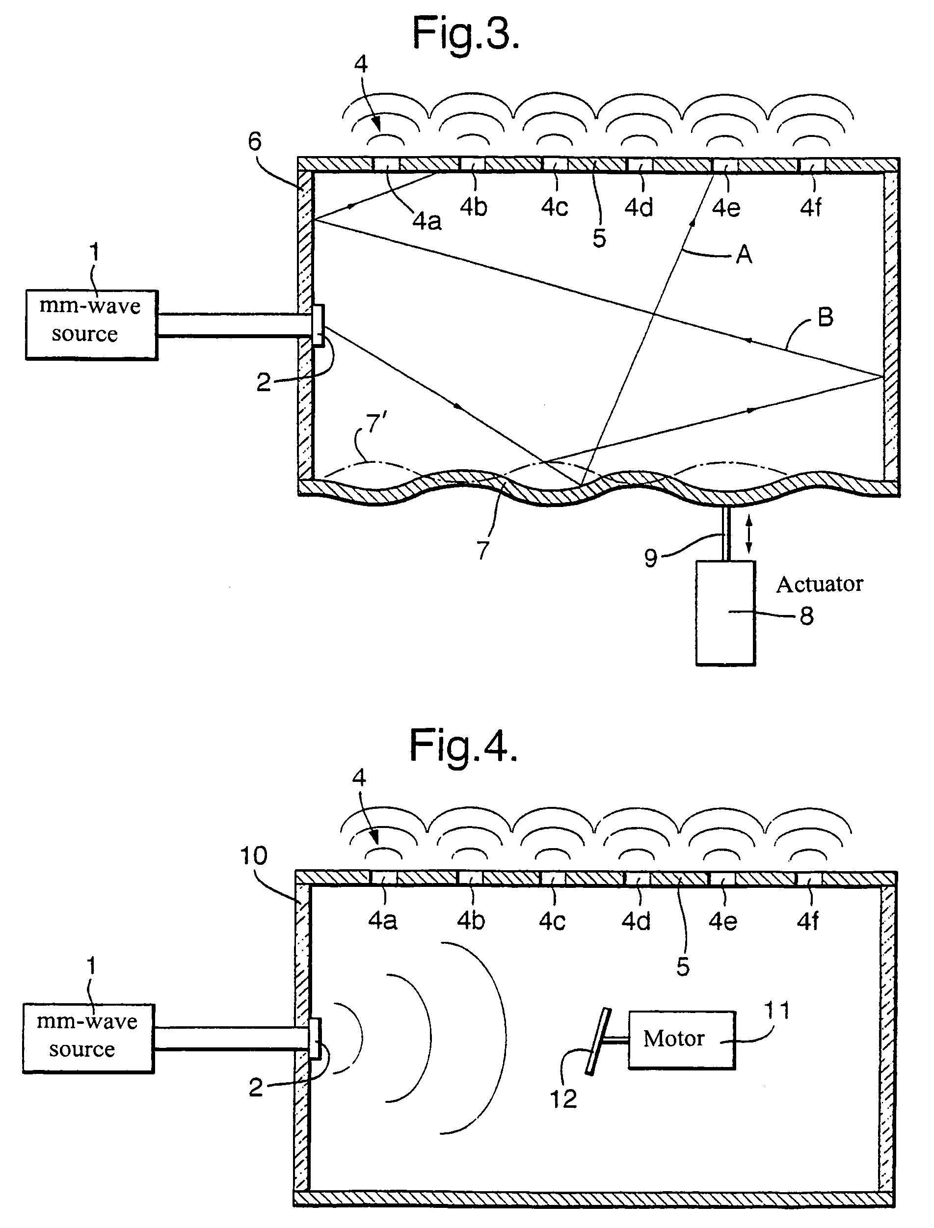
[0040]FIG. 2 shows the current invention. Primary source 1 is connected to container 6 such that the output of source 1 is within the container 5, as shown in FIG. 1. The container 6 is generally similar to that shown in FIG. 1 but is arranged such that one internal wall 7 is able to flex when driven by an actuator 8. Actuator 8 has a connection rod 9 coupled to the wall 7, and this connection rod 9 moves in and out as indicated by the arrows. Such movement of the rod 9 will cause the wall 7 to move, as shown in exaggerated form in FIG. 2. Typically, flexure of the wall 7 of even as little as a millimeter is sufficient to change the radiation field state or states within the container enough to have the effect of changing the radiation power spatial variation from the illumination system. Although actuator 8 is shown positioned outside the container 6, it may equally well be positioned within the container 6.

[0041]The actuator is preferably arranged to flex the wall 7 repeatedly at ...

second embodiment

[0044]FIG. 4 shows the current invention. Here, a primary source 1 again has an output 2 that feeds into a container 10. The container 10 is similar to that shown in FIG. 1, having exit apertures 4, and metallic inside walls. However, in this embodiment the container 10 also contains an electric motor 11 coupled to a skew-mounted metallic disk 12. The disk 12 is mounted such that it is in the path of at least some of the radiation from output 2. In practice, the disk can be mounted in any convenient location within the container 10.

[0045]The motor 11 is arranged to rotate the disk 12 when the illuminator is in use. Radiation that hits the disk will then be reflected away according to the position of the disk at that instant. As the disk rotates the radiation will reflect within the container 10 in different modes, and so the illumination spatial variation will be continuously changing. The motor is preferably arranged to rotate at a rate high enough to ensure that the modal change w...

fourth embodiment

[0047]FIG. 5 shows the current invention. A primary source 1 is shown connected to a container 10, the container 10 being generally similar to that of the container 10 of FIG. 4. The output of source 1 feeds into a millimeter wave switch box 13 that has four individual outputs 14a-14d. Switching circuitry within the switch box is able to select which of the four outputs 14 the energy from the source 1 is directed towards. The switch box 13 is preferably a P.I.N diode switched device, as this is capable of switching very rapidly. Millimeter wave switches suitable for this application are manufactured by Millitech, based at Northampton, Mass. 01060, USA. Electromechanical switches are also suitable for implementing this embodiment, but cannot switch as rapidly.

[0048]In use, the primary source 1 provides energy at the wavelength of interest to the switch box 13 which, at any given time, is arranged to direct the energy to one of the four outputs 14. Output 14d is shown emitting radiati...


PUM


Abstract

An improved millimeter wave illumination system includes at least one primary source of millimeter wave radiation, a reflecting surface and a baffle comprising a plurality of exit apertures arranged such that at least some of the radiation from the source is reflected from the reflective surface before proceeding to the baffle, characterized in that means are incorporated for generating a plurality of radiation field states within a pre-determined time interval. The baffle, source and reflector are preferably packaged into a container with the exit apertures providing an illumination output. The generation of the plurality of radiation field states provides an illumination at the illuminator output that is less spatially variable when integrated over the pre-determined time interval. Embodiments of the invention show means for generating the plurality of radiation field states including relative movement of the reflective surface, variable positioning of the source with respect to the reflective surface, and including multiple sources within a single system.

Description

[0001]This application is the US national phase of international application PCT / GB2005 / 001181, filed 24 Mar. 2005, which designated the U.S. and claimed priority of GB 0407511.5, filed 2 Apr. 2004, the entire contents of each of which are hereby incorporated by reference.BACKGROUND OF THE INVENTION[0002]1. Field of Invention[0003]This invention relates to systems and methods used for providing millimeter wave and sub-millimeter wave illumination of a scene. In particular, it relates to illuminators that are used primarily indoors, but also have utility in outdoor environments.[0004]2. Discussion of Prior Art[0005]Systems capable of producing images of a scene based on millimeter wave (or thereabouts) radiation emitted from the scene are becoming more commonplace as the technology used in such systems matures. These imaging systems are able to detect the energy levels at these wavelengths within a scene at a resolution fine enough to produce images of a quality suitable for many tas...

Claims


Application Information

Patent Timeline
IPC IPC(8): G01S13/88G01S7/35G01S13/89H01Q21/00G01S13/00H01Q21/06H01Q13/18G01V8/00G01S7/02G01S7/282
CPCG01S13/89G01S7/024G01S7/282
Inventor COWARD, PETER RSALMON, NEIL A
Owner QINETIQ LTD
Why Eureka
Try Eureka