
Bandwidth control apparatus, bandwidth control method, bandwidth control system, and bandwidth allocating apparatus

a control apparatus and control method technology, applied in the direction of data switching networks, data switching details, multiplex communication, etc., can solve the problems of unrecognized bandwidth control techniques, etc., to achieve accurate fairness, effectively use all bandwidths, and simple constitution

Inactive Publication Date: 2010-08-17
NEC CORP
View PDF12 Cites 6 Cited by
  • Summary
  • Abstract
  • Description
  • Claims
  • Application Information

AI Technical Summary

Benefits of technology

The present invention provides a bandwidth control system and method for a data transmission system. The system includes multiple bandwidth control apparatuses that can communicate with each other in cascade. Each bandwidth control apparatus can acquire the bandwidth state of its own access lines and other access lines in real-time, and allocate transmission bandwidth accordingly. This allows for effective utilization of bandwidths and fairness among the access lines. The bandwidth control apparatus includes a first unit to collect bandwidth states, a second unit to collect bandwidth states in other control apparatuses, and a control unit to allocate transmission bandwidth and control transmission bandwidths of the access lines. The invention provides a simple and efficient solution for bandwidth control in a data transmission system.

Problems solved by technology

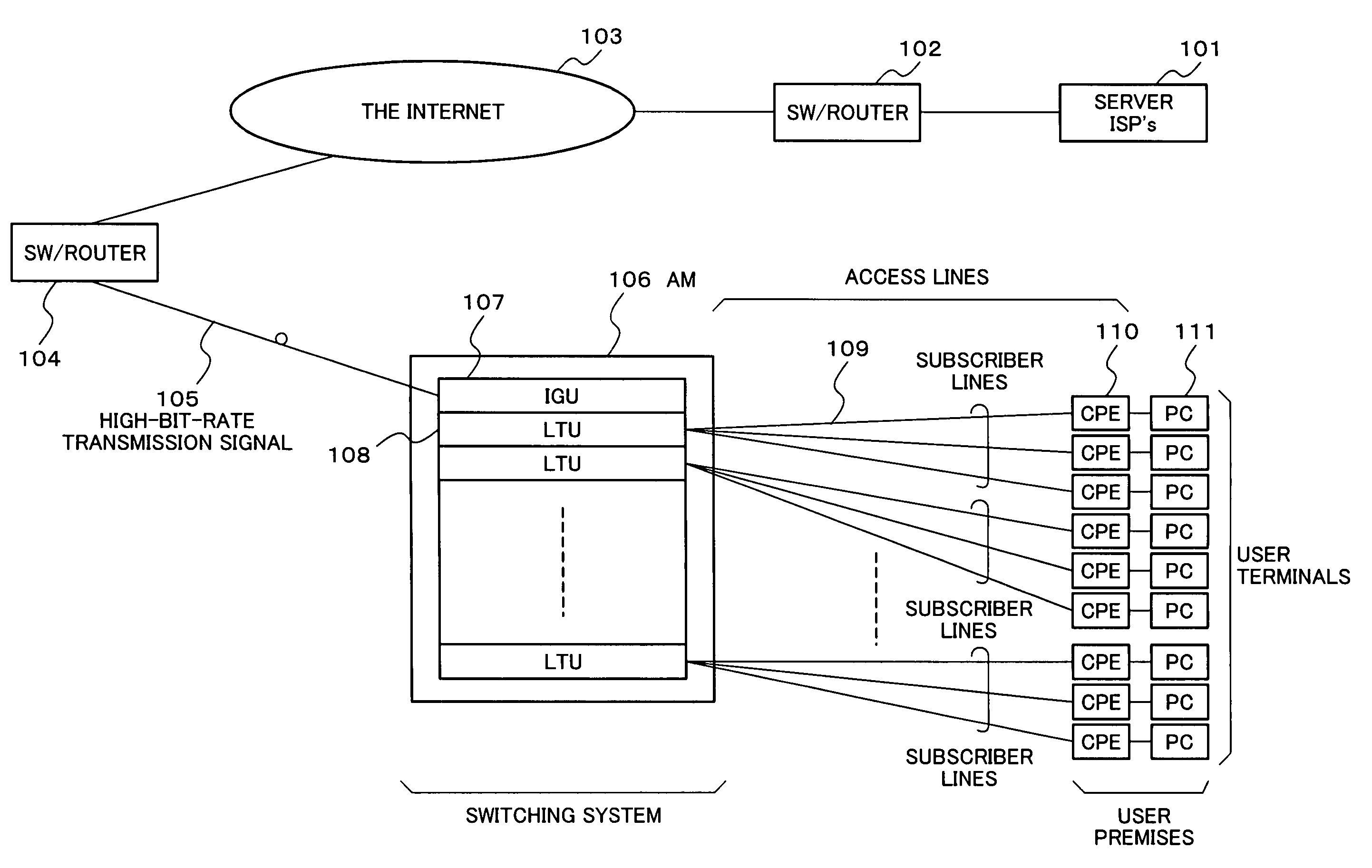
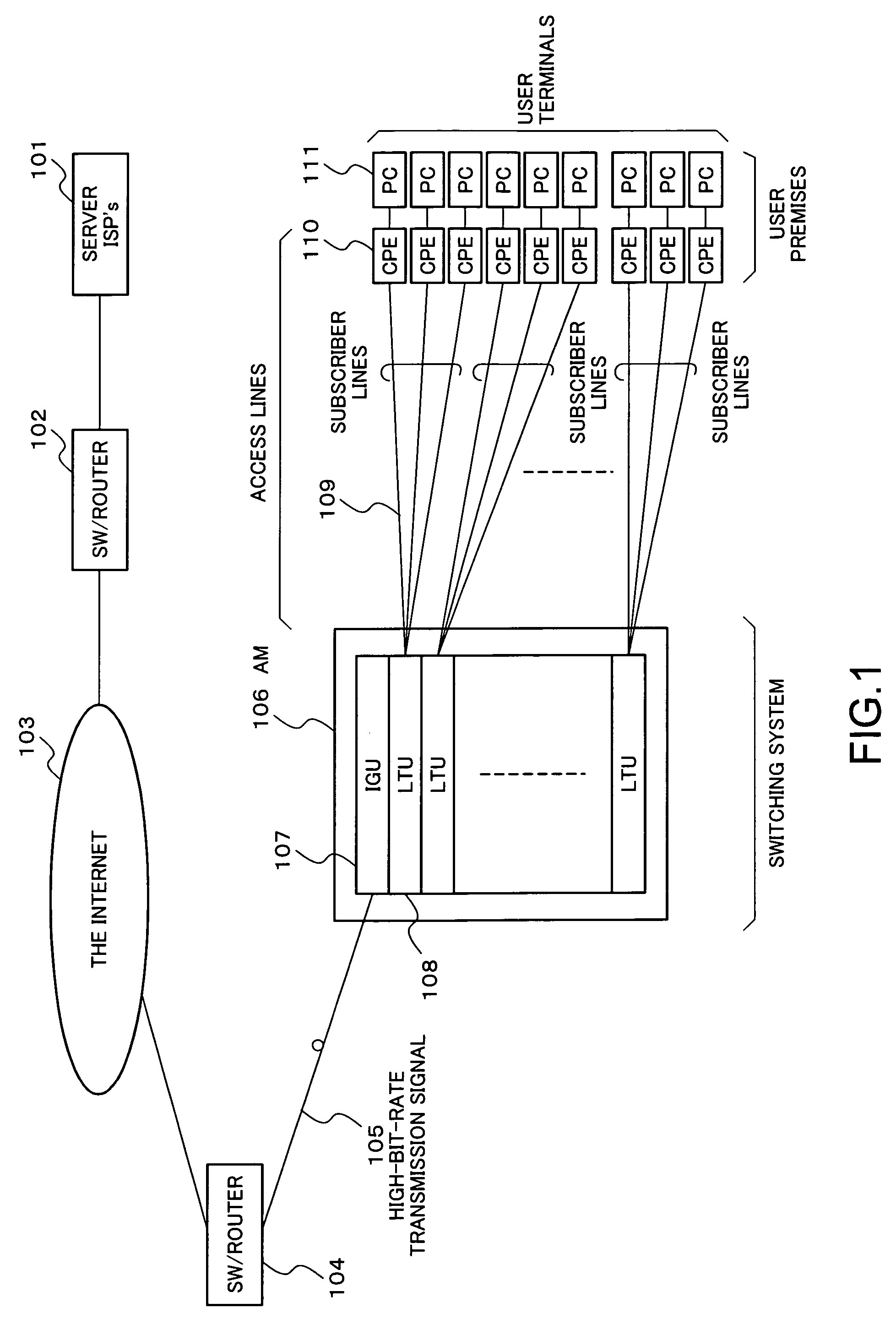
However, in order to realize this idea, a constitution of the access multiplexer 106 is inevitably complicated.
However, the document does not disclose a technique related to bandwidth control.

Method used


Image

  • Bandwidth control apparatus, bandwidth control method, bandwidth control system, and bandwidth allocating apparatus
  • Bandwidth control apparatus, bandwidth control method, bandwidth control system, and bandwidth allocating apparatus
  • Bandwidth control apparatus, bandwidth control method, bandwidth control system, and bandwidth allocating apparatus

Examples


Embodiment Construction

[0036]A bandwidth control system according to a first exemplary aspect of the present invention will be schematically explained.

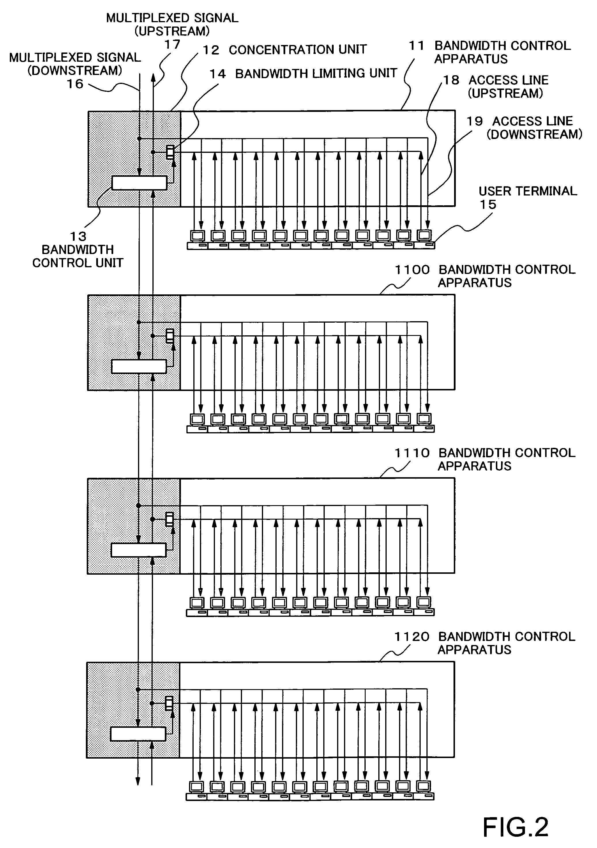
[0037]FIG. 2 is a diagram showing a system constitution of the bandwidth control system according to the first exemplary aspect of the present invention. As shown in FIG. 2, in the bandwidth control system according to this exemplary aspect, a plurality of bandwidth control apparatuses 11, 1100, 1110, and 1120 for controlling bandwidth states of data traffics flowing on access lines 18 and 19 are provided, and the respective bandwidth control apparatuses are connected in cascade. Each bandwidth control apparatus accommodates a plurality of user terminals 15, which perform data communication via a network (not shown), through the access lines 18 and 19. The respective bandwidth control apparatuses correspond to the Access Multiplexer (AM) 106 referred to in FIG. 1. The respective bandwidth control apparatuses have a function of terminating the respective acc...


PUM


Abstract

A bandwidth control apparatus which can reflect current operation states or effective rates of the access lines on bandwidth distribution is realized for effective utilization of bandwidths in a subscriber data transmission system. In a plurality of bandwidth control apparatuses accommodating a plurality of access lines in a bandwidth control system, multiplexed signal lines of respective bandwidth control apparatuses are connected to one another in cascade. Each bandwidth control apparatus acquires a bandwidth state of the access lines in the own apparatus and notifies the other apparatuses of the bandwidth state of the own apparatus having been acquired. Therefore, the bandwidth control apparatus can allocate a transmission bandwidth to be controlled in the own apparatus using a ratio of the bandwidth state occupied by the own apparatus to a total bandwidth states occupied in the bandwidth control system, and can control transmission bandwidths of the respective access lines accommodated in the own apparatus.

Description

BACKGROUND OF THE INVENTION[0001]1. Field of the Invention[0002]The present invention relates to a bandwidth control apparatus, a bandwidth control method, a bandwidth control system, and a bandwidth allocating apparatus for data transfer in a subscriber data transmission system, and, more particularly to a bandwidth control apparatus, a bandwidth control method, a bandwidth control system, and a bandwidth allocating apparatus applied to an x Digital Subscriber Line (x DSL: ‘x’ is a generic term representing ‘Asymmetric’, ‘Symmetric’, and ‘Very high-bit-rate’) and Fiber To The x (FTTX: ‘x’ is agenericterm representing ‘Building’, ‘Curb’, ‘Cabinet’, and ‘Home’).[0003]2. Description of the Related Art[0004]The x DSL uses a metallic cable such as a telephone line for a transmission medium serving as an access line to make it possible to perform high-bit-rate data transmission at several Megabits / second, and the FTTx uses an optical fiber cable for a transmission medium to make it possi...

Claims


Application Information

Patent Timeline
Patent Type & Authority Patents(United States)
IPC IPC(8): H04L12/56H04L12/02H04L47/762
CPCH04L12/5695H04L47/11H04L47/15H04L47/762H04L47/822H04Q3/64H04L12/2856H04Q2213/13039H04Q2213/13164H04Q2213/13166H04Q2213/13204H04Q2213/13292H04Q2213/13298H04Q2213/13332H04Q2213/13362H04Q2213/13387H04Q2213/13389H04L47/70
Inventor OZAKI, HIROKAZU
Owner NEC CORP
Learn More