Field emission cathode and x-ray tube embodying same

a field emitter and cathode technology, applied in the direction of discharge path tubes, discharge tubes/lamp details, electric discharge tubes, etc., can solve the problems of short service life of field emitters. , to achieve the effect of long service life and high durability

Inactive Publication Date: 2010-08-17
SIEMENS HEALTHCARE GMBH
View PDF8 Cites 9 Cited by
  • Summary
  • Abstract
  • Description
  • Claims
  • Application Information

AI Technical Summary

Benefits of technology

[0011]An object of the present invention to provide a field emission cathode that is highly durable and has a long service life.
[0012]Furthermore, it is an object of the present invention to provide an x-ray tube with a field emission cathode that is highly durable and has a long service life.
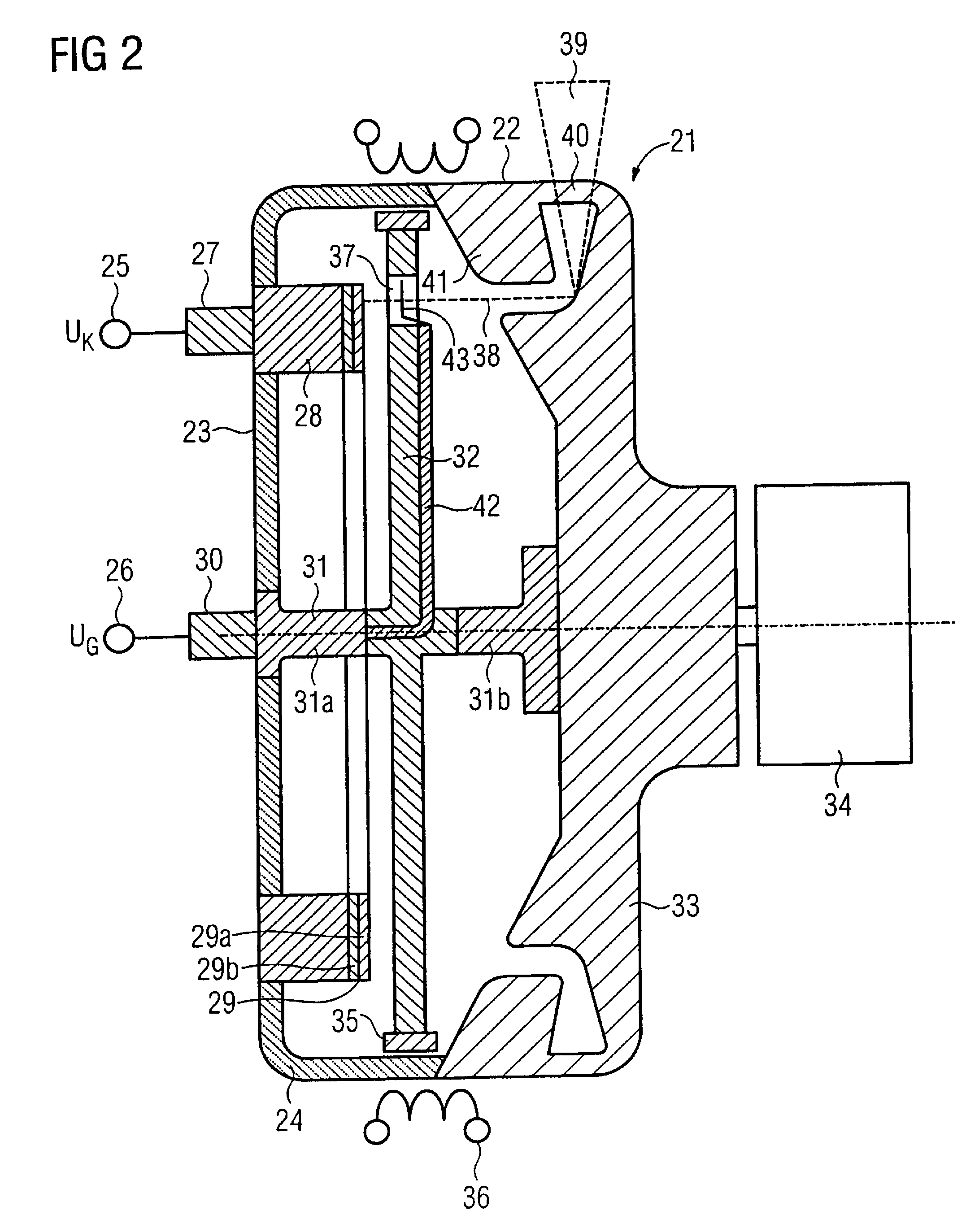
[0014]In the field emission cathode according to the invention, the field emitter and the extraction grid are moveable relative to one another, so only the region of the field emitter over which the extraction grid is presently located emits electrons. In the field emission cathode according to the invention, the current density can be markedly increased without reducing the lifespan due to the higher load. If the available increase of the current density is not used, the field emission cathode according to the invention then exhibits a distinctly longer lifespan. The emission current in the field emission cathode according to the invention can be adjusted in a known manner through the grid voltage. In addition to a quick activation, high electron currents can be achieved.
[0028]The x-ray tube according to the invention has a field emitter and an extraction grid that are moved relative to one another, and only the region of the field emitter over which the extraction grid is currently located emits electrons. In the x-ray tube according to the invention, the current density can clearly be increased without reducing the lifespan of the field emitter due to this higher load. If a possible increase of the current density is foregone, the field emission cathode of the x-ray tube according to the invention then exhibits a distinctly longer lifespan. In the field emission cathode of the x-ray tube according to the invention, the emission current can be adjusted in a known manner through the grid voltage. High electron currents can therefore be achieved in addition to a fast control.
[0039]An embodiment of the x-ray tube according to the invention in which the field emitter is executed as a Spindt emitter can also be advantageous for specific application fields.

Problems solved by technology

Such thermionic emission has the disadvantage that switching of the heating current requires several seconds since the heating of the thermionic emitter is slow.
If the current density is increased to a few A / cm2, the lifespan of the field emitter is limited.
The manufacture of such emitter modules is complicated and consequently is expensive.
Therefore this concept can only be realized with technical difficulty in rotating anode x-ray tubes.

Method used


Image

  • Field emission cathode and x-ray tube embodying same
  • Field emission cathode and x-ray tube embodying same
  • Field emission cathode and x-ray tube embodying same

Examples


Embodiment Construction

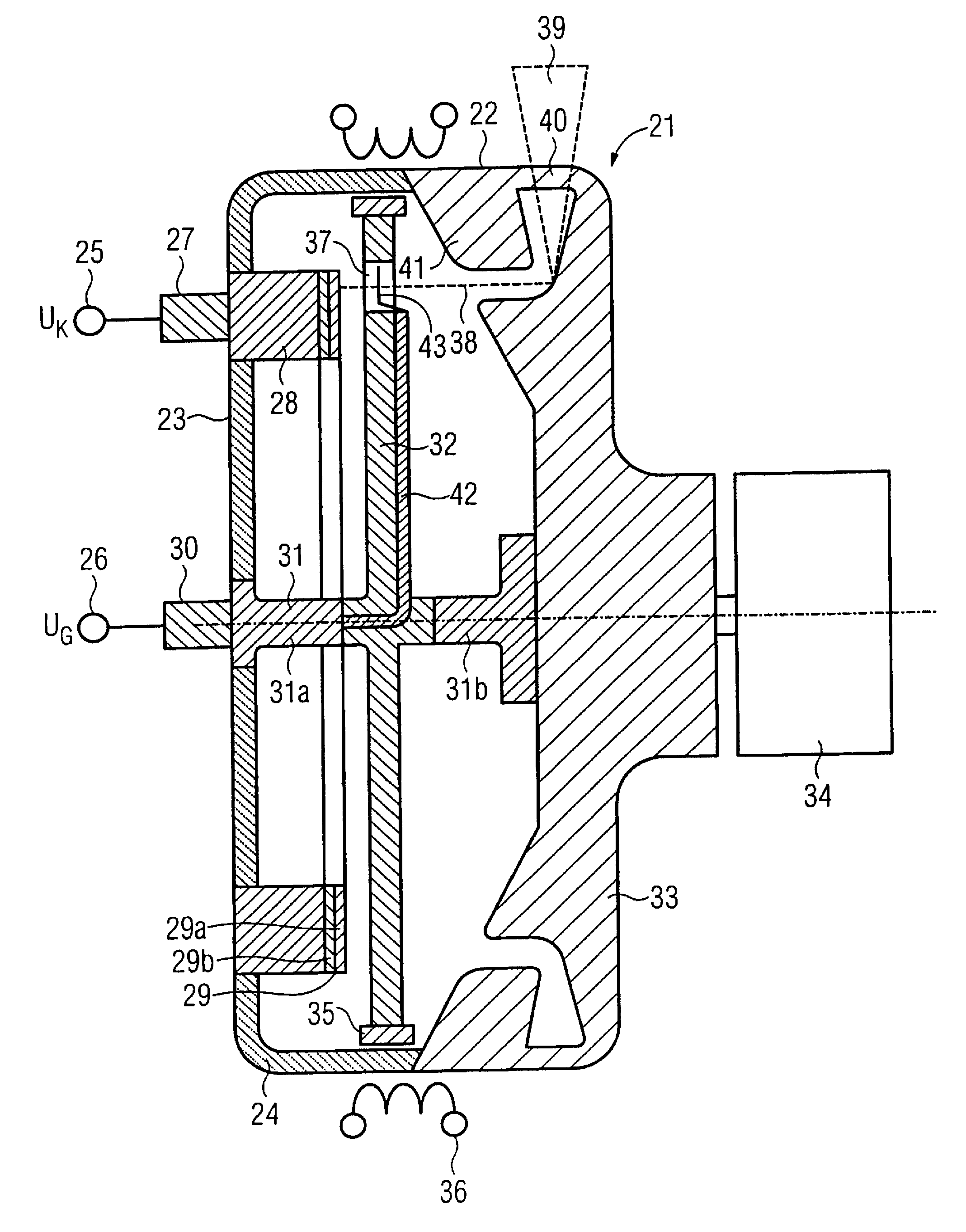
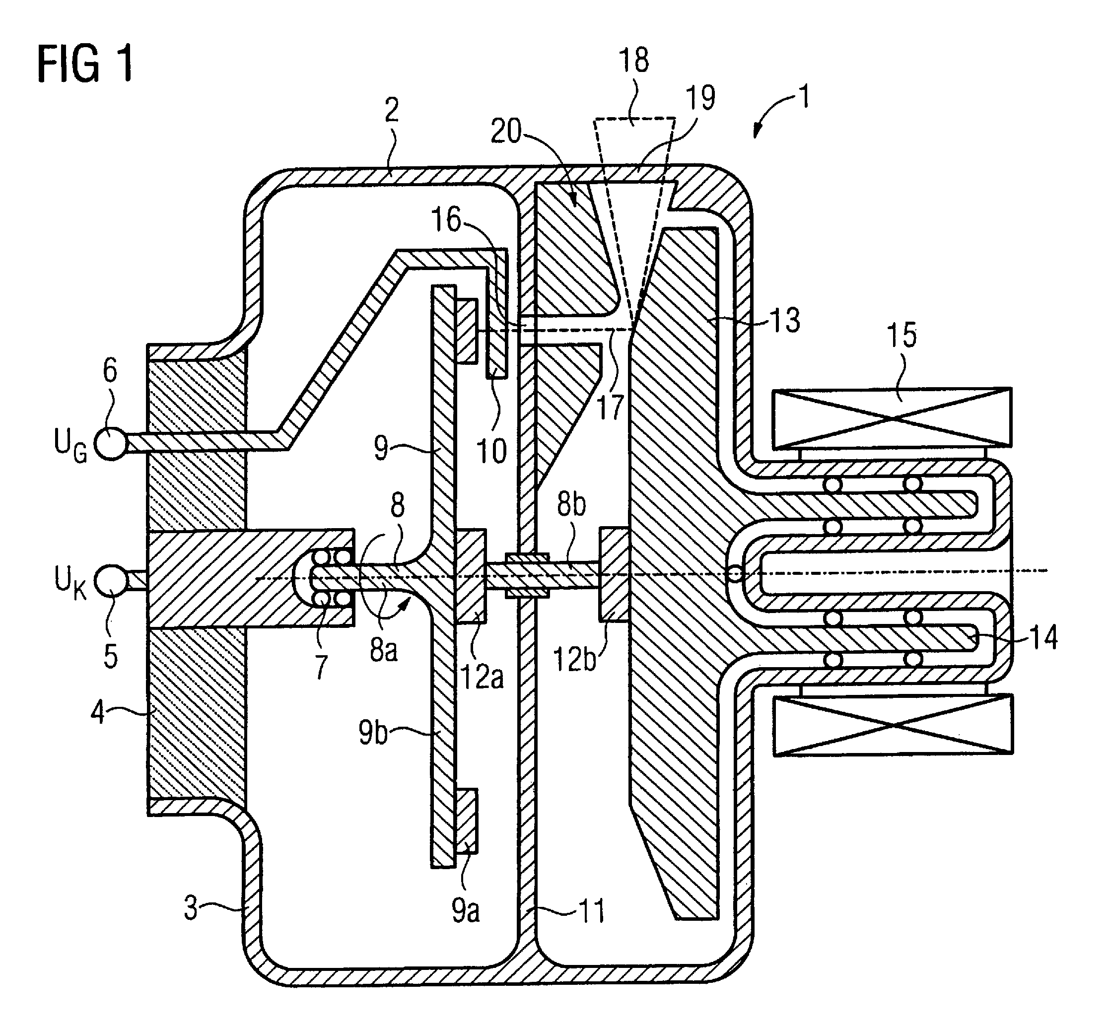
[0042]An x-ray tube 1 that is executed as a rotary anode x-ray tube is shown in FIG. 1.

[0043]The x-ray tube 1 has a stationary vacuum housing 2 with a high-voltage side 3 that possesses an insulating body 4 made of ceramic.

[0044]The x-ray tube 1 is mounted in a known manner in a radiator housing (now shown). A coolant liquid is located between the vacuum housing 2 and the radiator housing.

[0045]A high voltage connection (terminal) 5 and a high voltage connection 6 are arranged in the insulating body 4. The high voltage connection 5 is at a cathode potential UK, for example −120 kV, and is connected to an electrically conductive bearing 7 in which a shaft 8 is mounted such that it can rotate. A field emitter 9 is arranged on the shaft 8 such that it is rotationally fixed.

[0046]The high voltage connection 6 is connected to a stationary extraction grid 10 at a grid potential UG that increases the negative cathode potential UK by an extraction potential UE of, for example, +2 kV. In the...


PUM


Abstract

A field emission cathode has a field emitter and an extraction grid, and the field emitter and the extraction grid can be moved relative to one another. Such a field emission cathode is highly durable and exhibits a longer lifespan. An x-ray tube has a field emission cathode composed of a field emitter and an extraction grid that can be moved relative to one another. Such an x-ray tube is highly durable and exhibits a longer lifespan.

Description

BACKGROUND OF THE INVENTION[0001]1. Field of the Invention[0002]The present invention concerns a field emission cathode as well as an x-ray tube with such a field emission cathode.[0003]2. Description of the Prior Art[0004]In x-ray tubes, thermionic emitters (advantageously made of tungsten, tantalum or rhenium) are conventionally used to generate the electron beam required for the generation of x-ray radiation. The thermionic emitter is heated to approximately 2,000° C., causing electrons to be thermionically emitted, and the emitted electrons accelerated toward an anode by an electrical potential of approximately 120 kV. X-ray radiation usable for imaging is created when the thermionically generated electrons strike the anode. Such a thermionic emitter is described in DE 27 27 907 C2, for example. Such thermionic emission has the disadvantage that switching of the heating current requires several seconds since the heating of the thermionic emitter is slow.[0005]As an alternative t...

Claims


Application Information

Patent Timeline
Patent Type & Authority Patents(United States)
IPC IPC(8): H01J35/00
CPCH01J3/021H01J35/065H01J35/26H01J35/305
Inventor FUERST, JENSPOPESCU, STEFANWITTMANN, GEORG
Owner SIEMENS HEALTHCARE GMBH
Why Eureka
Try Eureka