Injection-locked frequency divider

a frequency divider and injection-locked technology, applied in pulse generators, instruments, pulse techniques, etc., can solve the problems of large power consumption, large power consumption, and disadvantages of conventional injection-locked frequency dividers, and achieve the effect of low operation voltage and convenient use in different kinds of hybrid ics

Inactive Publication Date: 2010-08-24
NAT TAIWAN UNIV OF SCI & TECH
View PDF5 Cites 2 Cited by
  • Summary
  • Abstract
  • Description
  • Claims
  • Application Information

AI Technical Summary

Benefits of technology

[0008]Accordingly, the present invention is directed to an injection-locked frequency divider, adapted for improving an injection locking range and achieving a low operation voltage by a phase difference of 180° between two input terminals for receiving an injection signal.
[0028]In general, the injection-locked frequency divider according to the present invention receives a differential injection signal with two input terminals. There is a phase difference of 180° between these two input terminals. Such an injection-locked frequency divider according to the present invention is featured with a wide injection locking range, and can be realized with a low operation voltage, and therefore can be conveniently used in different kinds of hybrid ICs.

Problems solved by technology

As such, such kinds of circuits usually consume a lot of power when being operated at a high frequency, and will configure ring oscillation frequency dividers when applied in ordinary digital circuits so that the frequency thereof would be restricted.
Therefore, in practical operation, a conventional injection-locked frequency divider typically has the disadvantages of smaller locking range and large power consumption.
In other words, such a restricted conventional injection-locked frequency divider can not be widely applied in so many kinds of hybrid ICs.

Method used


Image

  • Injection-locked frequency divider
  • Injection-locked frequency divider
  • Injection-locked frequency divider

Examples


Embodiment Construction

[0036]Reference will now be made in detail to the present preferred embodiments of the invention, examples of which are illustrated in the accompanying drawings. Wherever possible, the same reference numbers are used in the drawings and the description to refer to the same or like parts. Further, when a member is described as being connected to or coupled to another member, it may be connected to or coupled to the another member, either directly or indirectly. On the contrary, when a member is defined as being directly connected to or coupled to another member, it excludes any third party member coupled therebetween.

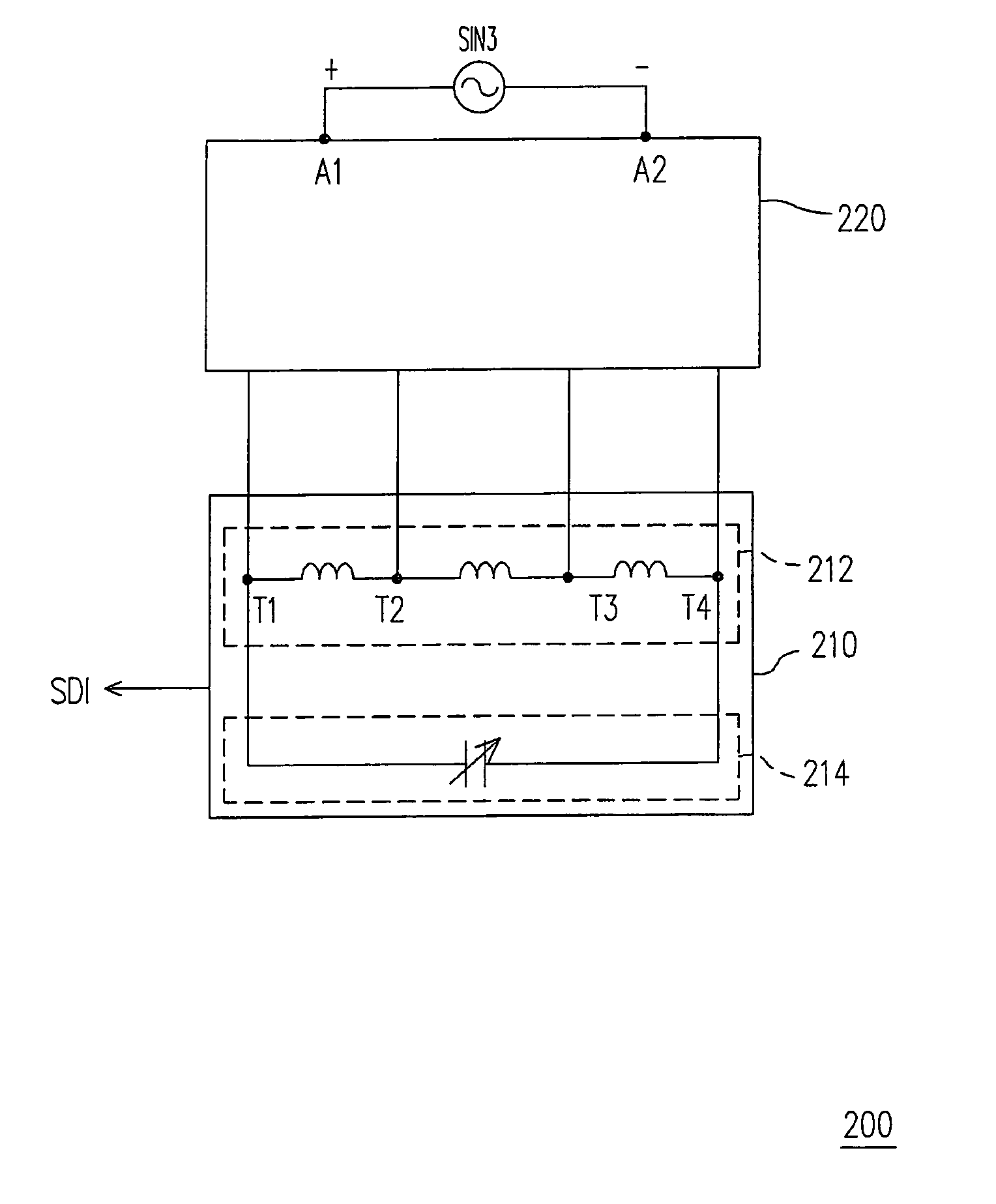
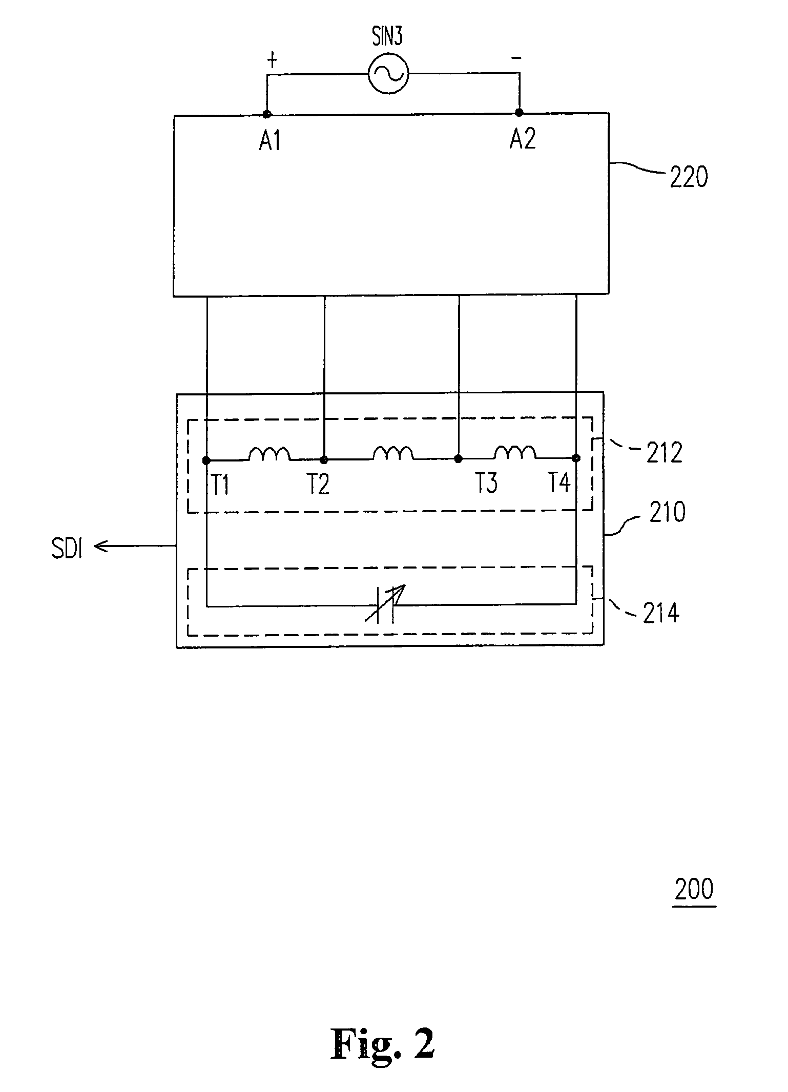
[0037]FIG. 2 is a circuit diagram illustrating an injection-locked frequency divider according to an embodiment of the present invention. Referring to FIG. 2, an injection-locked frequency divider 200 adapted for dividing a frequency of an injection signal SIN3, and obtaining a frequency divided signal SDI is shown. The injection-locked frequency divider 200 includes a s...


PUM


Abstract

An injection-locked frequency divider for dividing a frequency of an injection signal and obtaining a frequency divided signal is provided. The injection-locked frequency divider includes a signal injection unit and an oscillator. The signal injection unit includes a first input terminal and a second input terminal for receiving the injection signal. The received injection signal exhibits a phase difference of 180° between the first input terminal and the second input terminal. The oscillator includes an inductor unit and a variable capacitance unit. The injection-locked frequency divider is featured with a wide injection locking range, and can be realized with a low operation voltage, and therefore can be conveniently used in different kinds of hybrid ICs.

Description

CROSS-REFERENCE TO RELATED APPLICATION[0001]This application claims the priority benefit of Taiwan application serial no. 97112275, filed on Apr. 3, 2008. The entirety of the above-mentioned patent application is hereby incorporated by reference herein and made a part of specification.BACKGROUND OF THE INVENTION[0002]1. Field of the Invention[0003]The present invention generally relates to an injection-locked frequency divider, and more particularly, to a differential injection-locked frequency divider.[0004]2. Description of Related Art[0005]Frequency dividers are widely used in hybrid integrated circuits (IC). For example, frequency dividers are critical components for multiplexers, phase-locked loops (PLL), and frequency synthesizers. Currently, responsive to the demands of consumers, and the variations of system technologies, injection-locked frequency dividers, which are more suitable for operations of high speed systems, have become outstanding among variety of frequency divid...

Claims


Application Information

Patent Timeline
Patent Type & Authority Patents(United States)
IPC IPC(8): H03B19/06
CPCH03B19/14H03B27/00H03B5/1212
Inventor JANG, SHENG-LYANGLIU, CHENG-CHEN
Owner NAT TAIWAN UNIV OF SCI & TECH
Why Eureka
Try Eureka