
Instrument for implanting vascular prostheses

a vascular prosthesis and instrument technology, applied in the field of instruments for implanting vascular prostheses, can solve the problems of not being able to correct or reverse the procedure, unable to place the stent into the instrument during implantation, and unable to achieve the placement of the stent in the stenosis, so as to achieve the effect of eliminating the risk of damage to the vascular prosthesis during loading, facilitating the loading process, and facilitating the loading

Active Publication Date: 2010-08-31
MERIT MEDICAL SYST INC
View PDF130 Cites 122 Cited by
  • Summary
  • Abstract
  • Description
  • Claims
  • Application Information

AI Technical Summary

Benefits of technology

[0010]Starting from the state of the art, the invention is based on the object to provide an instrument with improved function for implanting vascular prostheses, which instrument ensures a very good placement of a vascular prosthesis in the body lumen and affords the possibility to re-compress and retrieve the vascular prosthesis so long as it has not yet fully exited the instrument.
[0014]Only when the outer tube has been retracted over the entire length of the stent, the stent expands fully deployed and is liberated. The predominantly lateral exiting motion of the stent in the stenosis site prevents the stent from shifting behind or in front of the constriction or even from springing. As a result, the stent can be accurately deployed, without longitudinal misalignment.
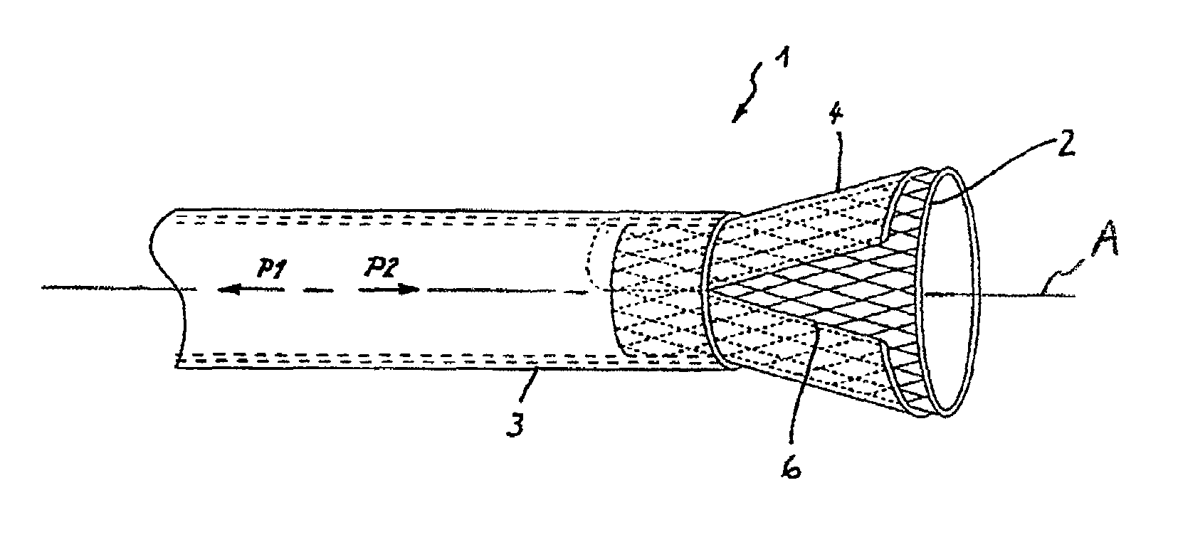
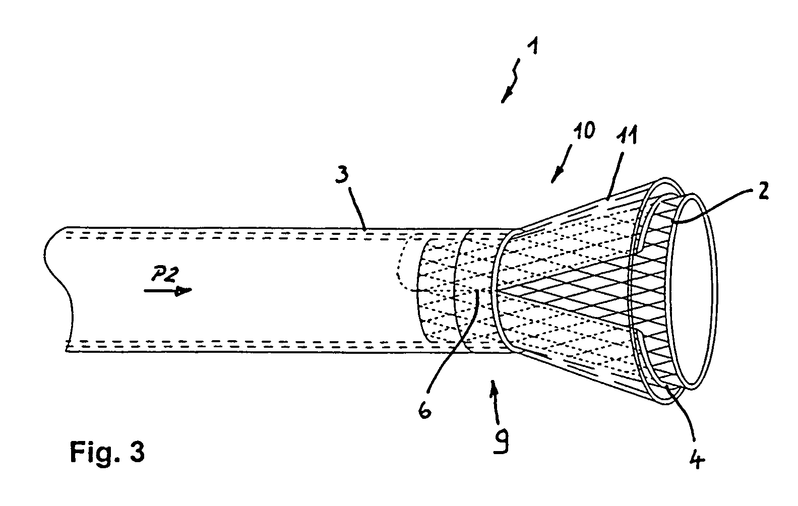
[0017]According to another feature of the invention, there is provided a loading aid at one end of the outer tube for radial constriction of a vascular prosthesis disposed in the inner tube. The loading aid supports loading of an instrument with a stent and simplifies the procedure. Such a loading aid may be configured, for example, in the form of a funnel piece. It may be detachably or non-detachably associated to the end of the outer tube. The stent is positioned in the area of the inner tube, which area has the longitudinal slot. Subsequently, the outer tube is placed with the loading aid over the inner tube. The loading aid constricts the inner tube and thereby compresses the stent until the latter is held completely in the instrument. The terminology in the art for this process is called “crimping”. Thereafter, the loading aid can be removed. The loading process is simple and the risk of damage to the vascular prosthesis during loading is basically eliminated. In this way, a stent can be loaded into the instrument even immediately prior to use so that the risk of aging and material fatigue of the stent are prevented.
[0018]When using nitrinol vascular prostheses, it may be suitable to make the loading aid coolable. The vascular prosthesis can then be cooled by the loading aid. As a consequence of the cooling effect, the stent is small and rigid so as to allow easy installation into the instrument.

Problems solved by technology

Positioning of the stent in the stenosis is, however, rather difficult because a precise placement of the stent in the stenosis requires a sensitive withdrawal of the instrument as the stent is freed.
A recovery of the stent into the instrument during implantation is not possible.
Also this type of instrument does not allow a correction or reversal of the procedure during implantation.
Another problem that should be mentioned here relates to the fact that the instruments are normally pre-loaded with a stent.
Thus, the material of the self-expanding stent can fatigue with time and loose their spring force so that their function is adversely affected.

Method used


Image

  • Instrument for implanting vascular prostheses
  • Instrument for implanting vascular prostheses
  • Instrument for implanting vascular prostheses

Examples


Embodiment Construction

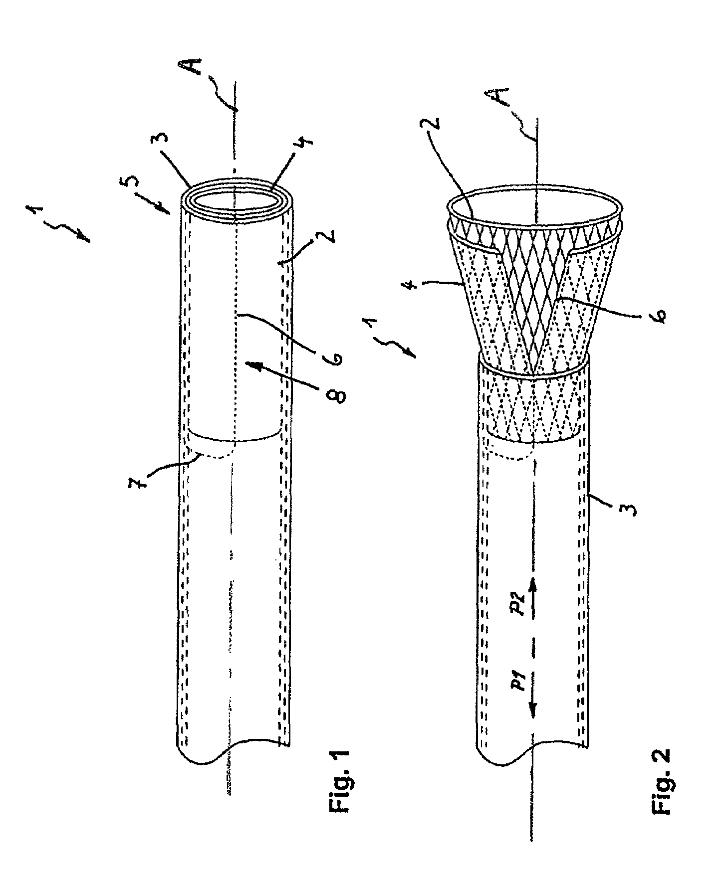
[0023]FIG. 1 shows an instrument 1 according to the invention with a contained stent 2. The instrument 1 includes an outer tube 3 and an inner tube 4. Both tubes 3, 4 are made of flexible material such as Teflon and are moveable relative to one another.

[0024]The inner tube 4 includes at its distal end a longitudinal slot 6. The longitudinal slot 6 terminates in a circular slot 7 which extends over a portion of the circumference of the inner tube 4. The longitudinal slot 6 extends substantially parallel to the longitudinal axis A of the inner tube 4, while the circular slot 7 extends substantially perpendicular to the longitudinal axis A. The stent 2 is received in this longitudinally slotted area 8 of the inner tube 4.

[0025]The stent 2 is compressed in the initial position before implantation and is enveloped by the inner tube 4. The outer tube 3 closes in this situation the inner tube 4 and the stent 2 so as to render an expansion of the stent 2 impossible.

[0026]FIG. 2 shows the im...


PUM


Abstract

An instrument for implanting an expandable cylindrical vascular prosthesis includes an outer tube and an inner tube which can be displaced relative to one another. The inner tube is longitudinally slotted on the distal end, at least in an area thereof, and ensheathes the stent with this area which includes the longitudinal slot. In order to implant the stent, the outer tube is retracted. The stent then expands with continuous retracting movement of the outer tube and the inner tube is pressed open along the longitudinal slot. Implantation is terminated, when the outer tube is retracted along the entire length of the stent. The implantation is reversible by pushing the outer tube forward, as long as the stent has not yet fully exited the instrument. In this way, the inner tube is constricted together with the stent, and compressed to an initial position.

Description

BACKGROUND OF THE INVENTION[0001]The invention relates to an instrument for implanting expandable cylindrical vascular prostheses, so called stents or endoprostheses. The instrument includes a flexible outer tube and an inner tube arranged therein, with the outer and inner tubes moveable relative to one another.[0002]Blockages of a vessel and constrictions of tubular body lumens, such as for example windpipe, bronchial tubes, esophagus, bile ducts, urinary tracts, blood vessels or the like, can be opened by surgical and non-surgical procedures. Non-surgical procedures involve the insertion of stents or endoprostheses in the area of the stenosis. Stents or endoprostheses are vascular supports which strengthen the inner vessel wall and are introduced through catheter technique into the vessel. Endoprostheses are referred to as ensheathed stents. In the following, the term stent is used consistently.[0003]Stents are available in a wide variety of different plastic, metal and hybrid con...

Claims


Application Information

Patent Timeline
IPC IPC(8): A61F2/06A61F2/95A61F2/97A61M25/12
CPCA61F2/95A61F2/97
Inventor FREITAG, LUTZ
Owner MERIT MEDICAL SYST INC
Learn More