
Methanol synthesis

Active Publication Date: 2010-08-31
JOHNSON MATTHEY PLC
View PDF14 Cites 50 Cited by
  • Summary
  • Abstract
  • Description
  • Claims
  • Application Information

AI Technical Summary

Problems solved by technology

This arrangement is, however, unsuitable for gases whose stoichiometric number (R), defined by the formula;
However, one of the difficulties with this approach is that for synthesis gases that are very deficient in H2, it is necessary to recover large quantities of H2 from the purge gas, and to have such a large flow of purge gas means either operating the synthesis loop at low pressure or having a low ratio of flow of recycle gas to flow of fresh synthesis gas.
Running the synthesis loop at low pressure is not attractive for large commercial scale plants due to the size of the pipework, vessel diameters, etc., whereas running with a low recycle ratio can impose restrictions on the methanol synthesis reactor that may be unacceptable.
For instance, a low recycle ratio means that using the circulating gas to cool the reaction, either in a quench cooled or tubular reactor, is impossible, so the only option is a steam-raising reactor.
This is an unattractive choice as this leads to poor utilisation of the volume within the shell of the reactor as well as the requirement for extremely thick, heavy tube sheets.
There is also a limit to the pressure at which steam can be raised, so utilisation of this steam may complicate the design of the steam system on such a plant so increasing cost and reducing operability and reliability.
However, the drawback to this arrangement is that some hydrogen is lost within the hydrogen recovery unit before it ever gets to the synthesis loop, and the synthesis gas, after enrichment with this hydrogen, will now have a stoichiometry number greater than 2, so the purge gas will now consist of a significant portion of unreacted H2.
Since the synthesis gas generation unit is the most expensive part of the plant, increased spending in this area is uneconomic.

Method used

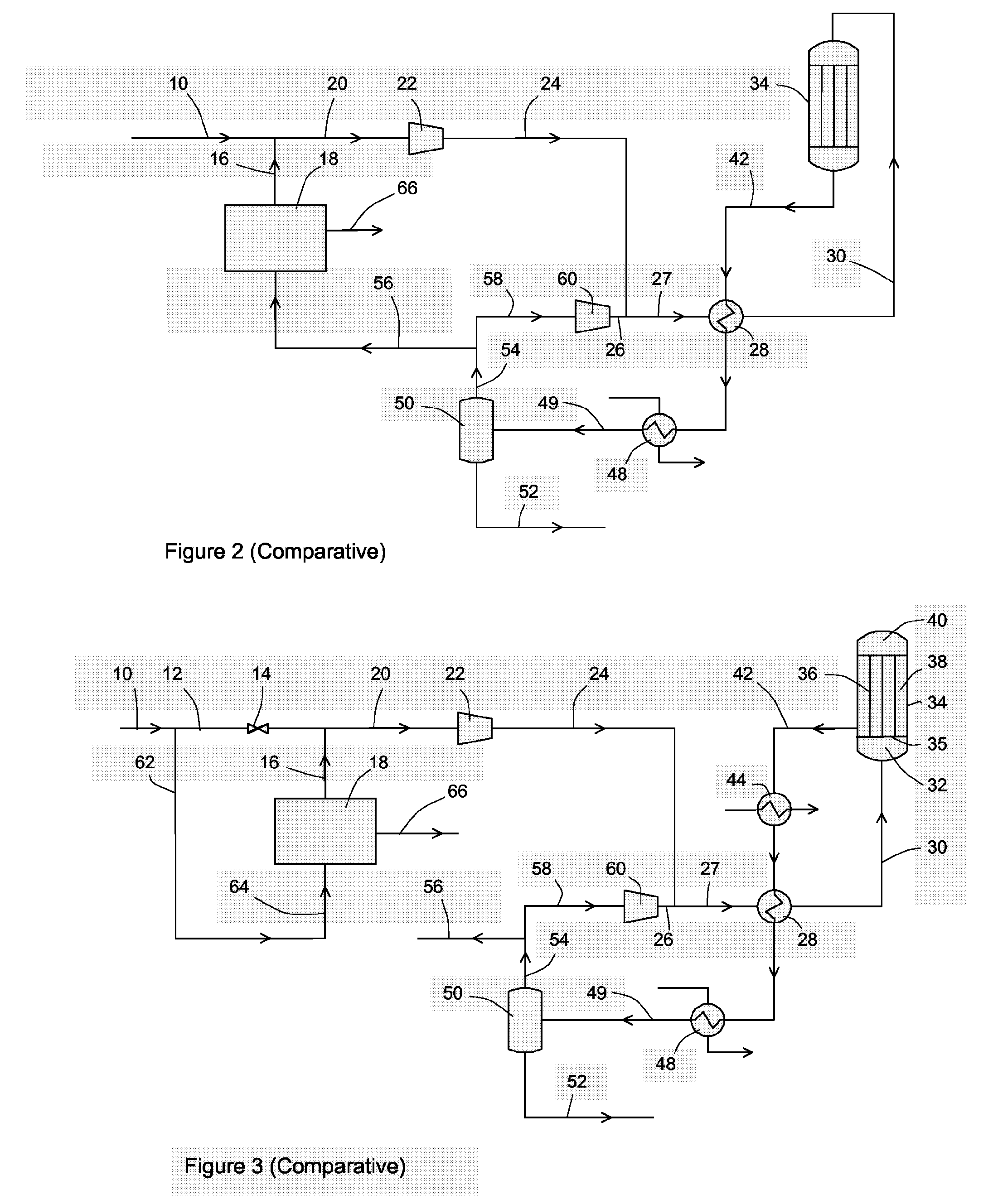

Image

  • Methanol synthesis
  • Methanol synthesis
  • Methanol synthesis

Examples


example 1

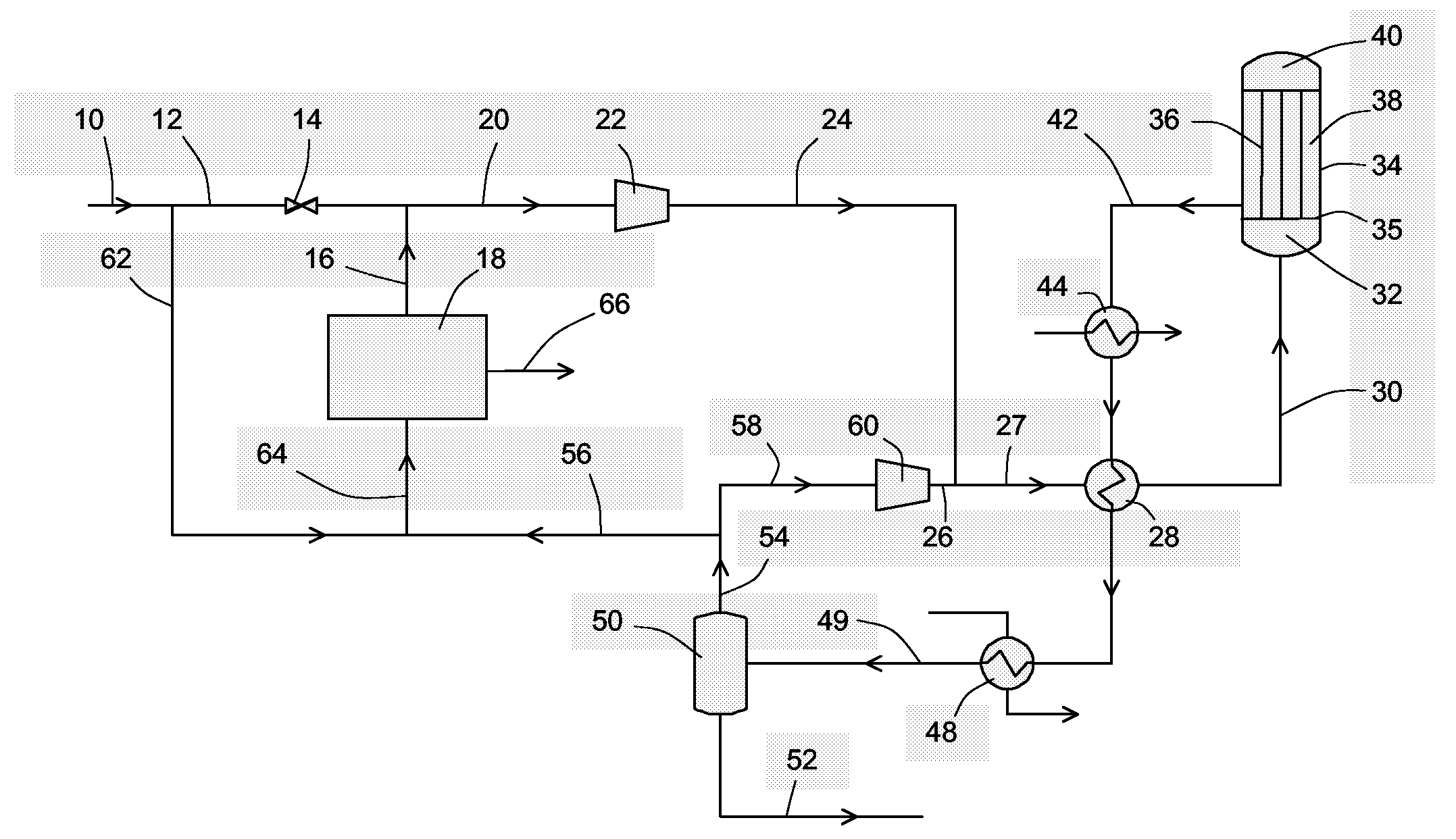
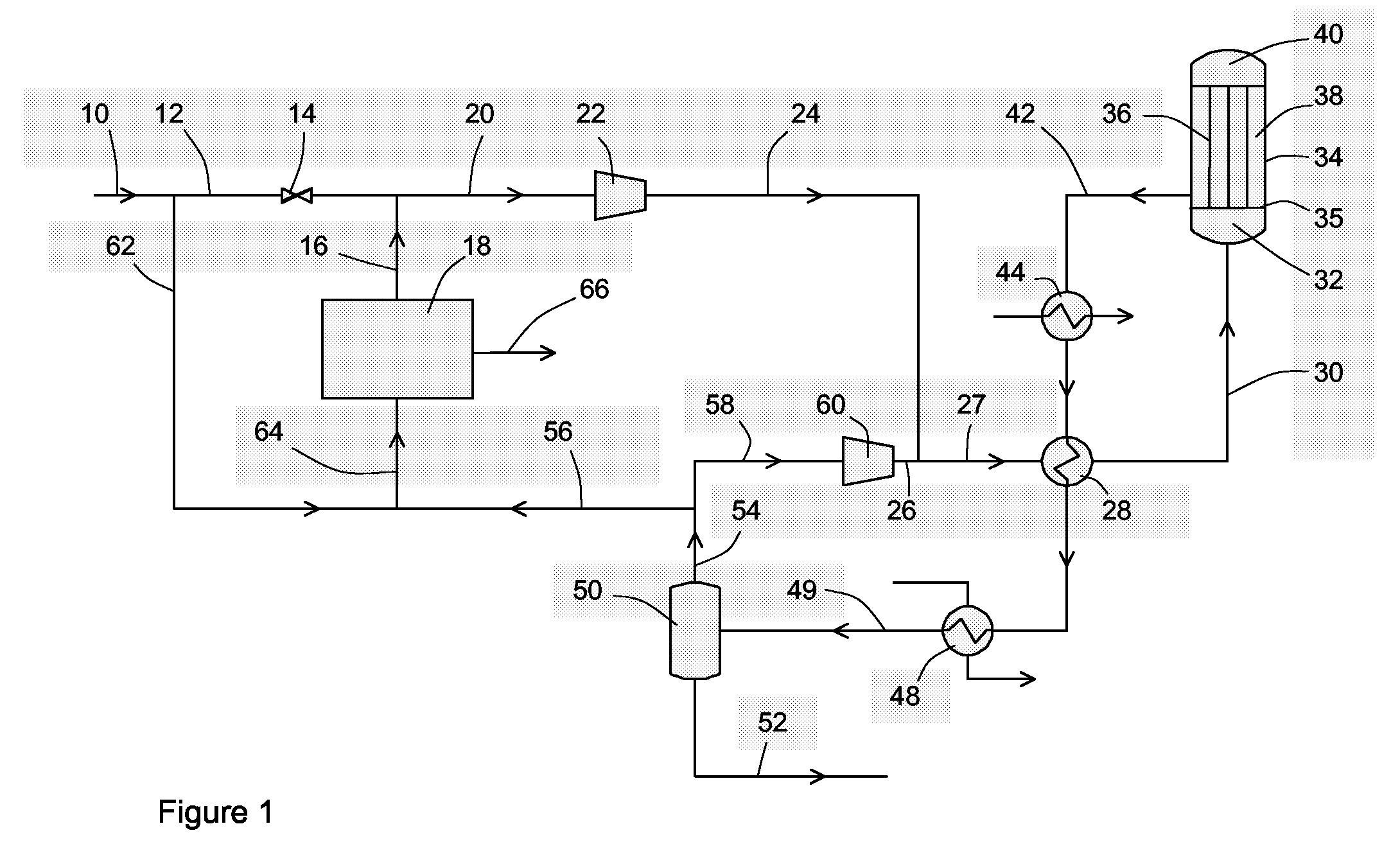
[0043]According to the embodiment depicted in FIG. 1.

[0044]

Stream106216203042585652Temperature [C.]45.045.045.044.9220.0255.045.045.045.0Pressure [bar]34.034.034.034.081.580.077.777.777.7Molar Flow [kgmole / h]15210.61181.01336.815366.475366.466877.160000.01583.15294.2Mass Flow [kg / h]18607314447269517432184449284448767017117683156637Hydrogen63.63%63.63%100.00%66.79%59.86%53.50%58.08%58.08%0.24%CO24.71%24.71%0.00%22.56%7.61%3.49%3.79%3.79%0.09%CO27.21%7.21%0.00%6.58%5.88%5.37%5.70%5.70%1.49%Methane3.15%3.15%0.00%2.88%19.46%21.93%23.70%23.70%1.27%Nitrogen0.79%0.79%0.00%0.72%5.44%6.13%6.64%6.64%0.11%Argon0.17%0.17%0.00%0.15%1.11%1.25%1.35%1.35%0.04%Methanol0.00%0.00%0.00%0.00%0.53%6.95%0.67%0.67%79.97%H2O0.34%0.34%0.00%0.31%0.11%1.38%0.06%0.06%16.78%Methanol production is high using a low volume of synthesis catalyst.


PUM

PropertyMeasurementUnit
Fractionaaaaaaaaaa
Fractionaaaaaaaaaa
Percent by volumeaaaaaaaaaa

Abstract

A process for synthesising methanol comprises the steps of: (i) reforming a hydrocarbon feedstock and separating water to generate a make-up gas comprising hydrogen and carbon oxides, the make-up gas mixture having a stoichiometric number, R, R=([H2]−[CO2]) / ([CO2]+[CO]) of less than 2.0, (ii) combining the make up gas with an unreacted synthesis gas to form a synthesis gas mixture, (iii) passing the synthesis gas through a bed of methanol synthesis catalyst to generate a product stream, (iv) cooling the product stream to recover a crude methanol stream from the unreacted synthesis gas, (v) removing a portion of the unreacted synthesis gas as a purge gas, and (vi) feeding the remaining unreacted synthesis gas to step (ii), wherein hydrogen is recovered from a portion of the purge gas and the make up gas, and the recovered hydrogen is included in the synthesis gas mixture.

Description

CROSS-REFERENCE TO RELATED APPLICATION[0001]This application is the U.S. National Phase application of PCT International Application No. PCT / GB2006 / 050096, filed May 9, 2006, and claims priority of British Patent Application No. 0510823.8, filed May 27, 2005.FIELD OF THE INVENTION[0002]This invention relates to methanol synthesis and in particular to methanol synthesis from a synthesis gas that is deficient in hydrogen.BACKGROUND OF THE INVENTION[0003]Methanol synthesis is generally performed by passing a synthesis gas comprising hydrogen, carbon oxides and any inert gases at an elevated temperature and pressure through one or more beds of a methanol synthesis catalyst, which is often a copper-containing composition. Methanol is generally recovered by cooling the product gas stream to below the dew point of the methanol and separating off the product as a liquid. The process is usually operated in a loop: thus the remaining unreacted gas stream is usually recycled to the synthesis r...

Claims


Application Information

Patent Timeline
IPC IPC(8): C07C27/00C07C29/151
CPCC07C29/1518C12C11/02C07C31/04Y02P20/129
Inventor FITZPATRICK, TERENCE JAMES
Owner JOHNSON MATTHEY PLC
Learn More