Magnetoresistive element with improved magentoresistance change amount and with free layer having improved soft magnetic characteristics

a free layer and magenta-resistance-enhancing technology, applied in the field of magnetoresistance elements, can solve the problems of insufficient magnetoresistance-enhancing amount of conventional cpp-gmr elements obtained so far, small magnetoresistance-enhancing amount, low output voltage proportional to the effect of magnetoresistance-enhancing amoun

Inactive Publication Date: 2010-08-31
TDK CORPARATION
View PDF17 Cites 0 Cited by
  • Summary
  • Abstract
  • Description
  • Claims
  • Application Information

AI Technical Summary

Benefits of technology

[0015]It is an object of the invention to provide a magnetoresistive element in which a current is fed in the direction intersecting each layer making up the magnetoresistive element, wherein the element has a great magnetoresistance change amount, and a free layer has an excellent soft magnetic property, and to provide a method of manufacturing such a magnetoresistive element, and to provide a magnetoresistive device, a thin-film magnetic head, a head gimbal assembly, a head arm assembly and a magnetic disk drive each of which incorporates the magnetoresistive element.
[0017]In the magnetoresistive element of the invention, the free layer has the first layer made of an alloy containing ‘a’ atomic percent cobalt and (100−a) atomic percent iron wherein ‘a’ falls within a range of 20 to 50 inclusive. As a result, it is possible to increase the magnetoresistance change amount of the magnetoresistive element and to make the free layer have excellent soft magnetic characteristics so that the absolute value of magnetostriction constant of the free layer is 1×10⁻⁶ or smaller, and that the coercivity of the free layer is 20×79.6 A / m or smaller.
[0027]In the invention, the free layer of the magnetoresistive element incorporates the first layer made of an alloy containing ‘a’ atomic percent cobalt and (100−a) atomic percent iron wherein ‘a’ falls within a range of 20 to 50 inclusive. In addition, the absolute value of magnetostriction constant of the free layer is 1×10⁻⁶ or smaller, and the coercivity of the free layer is 20×79.6 A / m or smaller. As a result, according to the invention, it is possible to increase the magnetoresistance change amount of the magnetoresistive element and to make the free layer have excellent soft magnetic characteristics.

Problems solved by technology

Therefore, the typical CPP-GMR element has a problem that the magnetoresistance change amount is small, wherein the magnetoresistance change amount is the product of the electrical resistance and the magnetoresistance change ratio (MR ratio).
Furthermore, in a read head using such a CPP-GMR element, the output voltage proportional to the magnetoresistance change amount is low, which is a practical problem of the CPP-GMR element.
However, the magnetoresistance change amount of conventional CPP-GMR elements obtained so far is not large enough.

Method used


Image

  • Magnetoresistive element with improved magentoresistance change amount and with free layer having improved soft magnetic characteristics
  • Magnetoresistive element with improved magentoresistance change amount and with free layer having improved soft magnetic characteristics
  • Magnetoresistive element with improved magentoresistance change amount and with free layer having improved soft magnetic characteristics

Examples


Embodiment Construction

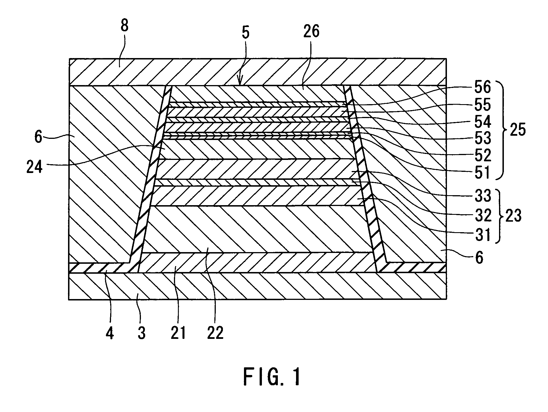
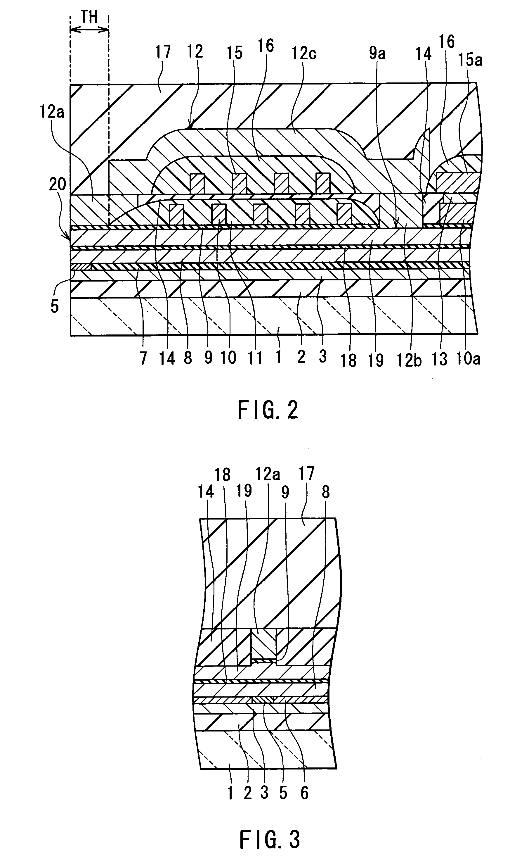
[0042]A preferred embodiment of the invention will now be described in detail with reference to the accompanying drawings. Reference is now made to FIG. 2 and FIG. 3 to describe the outlines of the configuration and a manufacturing method of a thin-film magnetic head of the embodiment of the invention. FIG. 2 illustrates a cross section of the thin-film magnetic head orthogonal to an air bearing surface and a substrate. FIG. 3 illustrates a cross section of a pole portion of the thin-film magnetic head parallel to the air bearing surface.

[0043]In the method of manufacturing the thin-film magnetic head of the embodiment, first, an insulating layer 2 made of an insulating material such as alumina (Al2O3) and having a thickness of 1 to 5 μm, for example, is formed by a method such as sputtering on a substrate 1 made of a ceramic such as aluminum oxide and titanium carbide (Al2O3—TiC). Next, a first shield layer 3 for a read head having a specific pattern and made of a magnetic material...


PUM

PropertyMeasurementUnit
coercivityaaaaaaaaaa
thicknessaaaaaaaaaa
thicknessaaaaaaaaaa

Abstract

A free layer of an MR element incorporates a first layer, a second layer, a third layer, a fourth layer, a fifth layer and a sixth layer that are stacked in this order on a nonmagnetic conductive layer. The absolute value of magnetostriction constant of the free layer is 1×10⁻⁶ or smaller. The coercivity of the free layer is 20×79.6 A / m or smaller. The first layer is made of an alloy containing ‘a’ atomic percent cobalt and (100−a) atomic percent iron wherein ‘a’ falls within a range of 20 to 50 inclusive. The second layer is made of an alloy containing ‘b’ atomic percent cobalt and (100−b) atomic percent iron wherein ‘b’ falls within a range of 70 to 90 inclusive. In addition, oxidation treatment is given to a surface of the second layer farther from the first layer.

Description

BACKGROUND OF THE INVENTION[0001]1. Field of the Invention[0002]The present invention relates to a magnetoresistive element and a method of manufacturing the same and to a magnetoresistive device, a thin-film magnetic head, a head gimbal assembly, a head arm assembly and a magnetic disk drive each of which incorporates the magnetoresistive element.[0003]2. Description of the Related Art[0004]Performance improvements in thin-film magnetic heads have been sought as areal recording density of magnetic disk drives has increased. A widely used type of thin-film magnetic head is a composite thin-film magnetic head that has a structure in which a write (recording) head having an induction-type electromagnetic transducer for writing and a read (reproducing) head having a magnetoresistive (MR) element for reading are stacked on a substrate.[0005]MR elements include: anisotropic magnetoresistive (AMR) elements utilizing an anisotropic magnetoresistive effect; giant magnetoresistive (GMR) elem...

Claims


Application Information

Patent Timeline
Patent Type & Authority Patents(United States)
IPC IPC(8): G11B5/33
CPCB82Y10/00G11B5/3929Y10T428/1171Y10T428/1121Y10T428/115G11B2005/3996
Inventor MIZUNO, TOMOHITOMIYAUCHI, DAISUKE
Owner TDK CORPARATION
Why Eureka
Try Eureka