Amorphous magnetic component, electric motor using same and method for manufacturing same

a technology of amorphous magnetic components and electric motors, applied in the direction of magnetic circuit rotating parts, magnetic bodies, magnetic circuit shapes/forms/construction, etc., can solve the problems of affecting the efficiency of the motor, requiring complex and expensive coil winding equipment, and a lot of time on winding operations, so as to improve the permeability, improve the permeability, and facilitate the insertion of magnetic components.

Inactive Publication Date: 2013-10-10
AMOTECH
View PDF12 Cites 14 Cited by
  • Summary
  • Abstract
  • Description
  • Claims
  • Application Information

AI Technical Summary

Benefits of technology

[0031]As described above, the present invention provides an amorphous magnetic component for use in a high-power, high-speed electric motor, in which amorphous metal materials are powdered, compressed, and molded, to thus be easily molded into magnetic components of a complex shape, and crystalline metal powder of excellent soft magnetic properties is added to the amorphous alloy powder, to thus promote improved permeability and improved packing density at the time of compression molding, and a method of manufacturing the amorphous magnetic component.
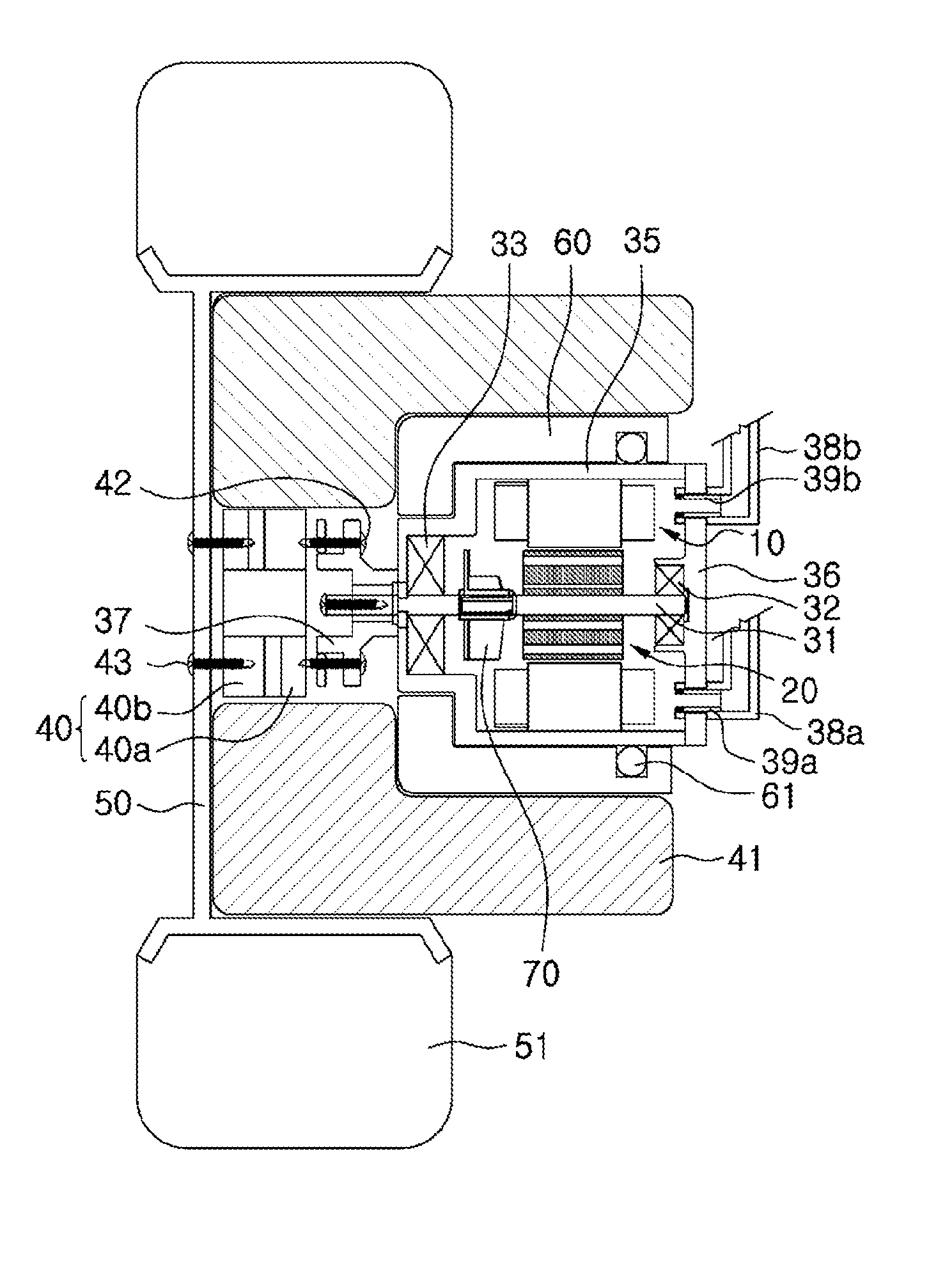
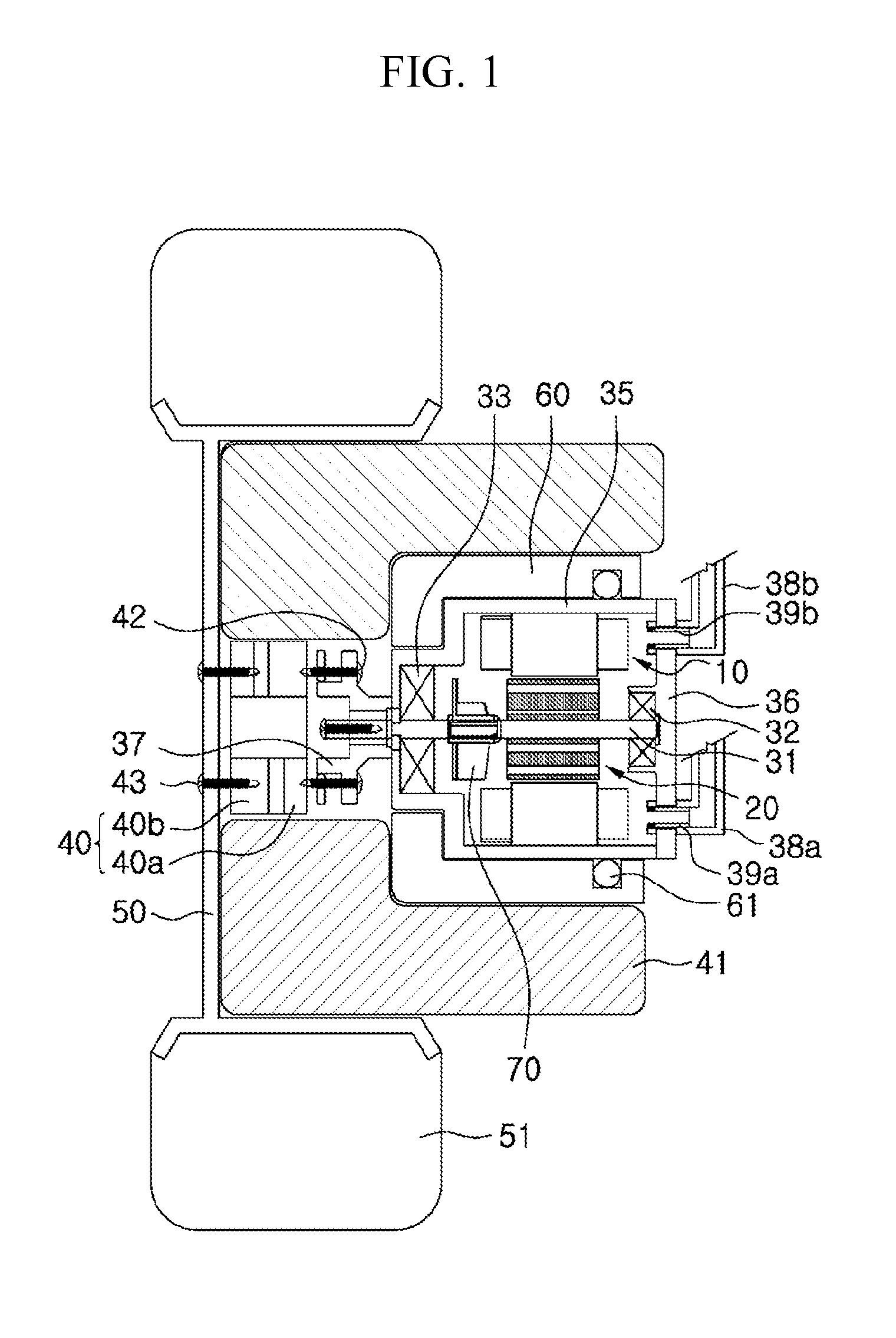
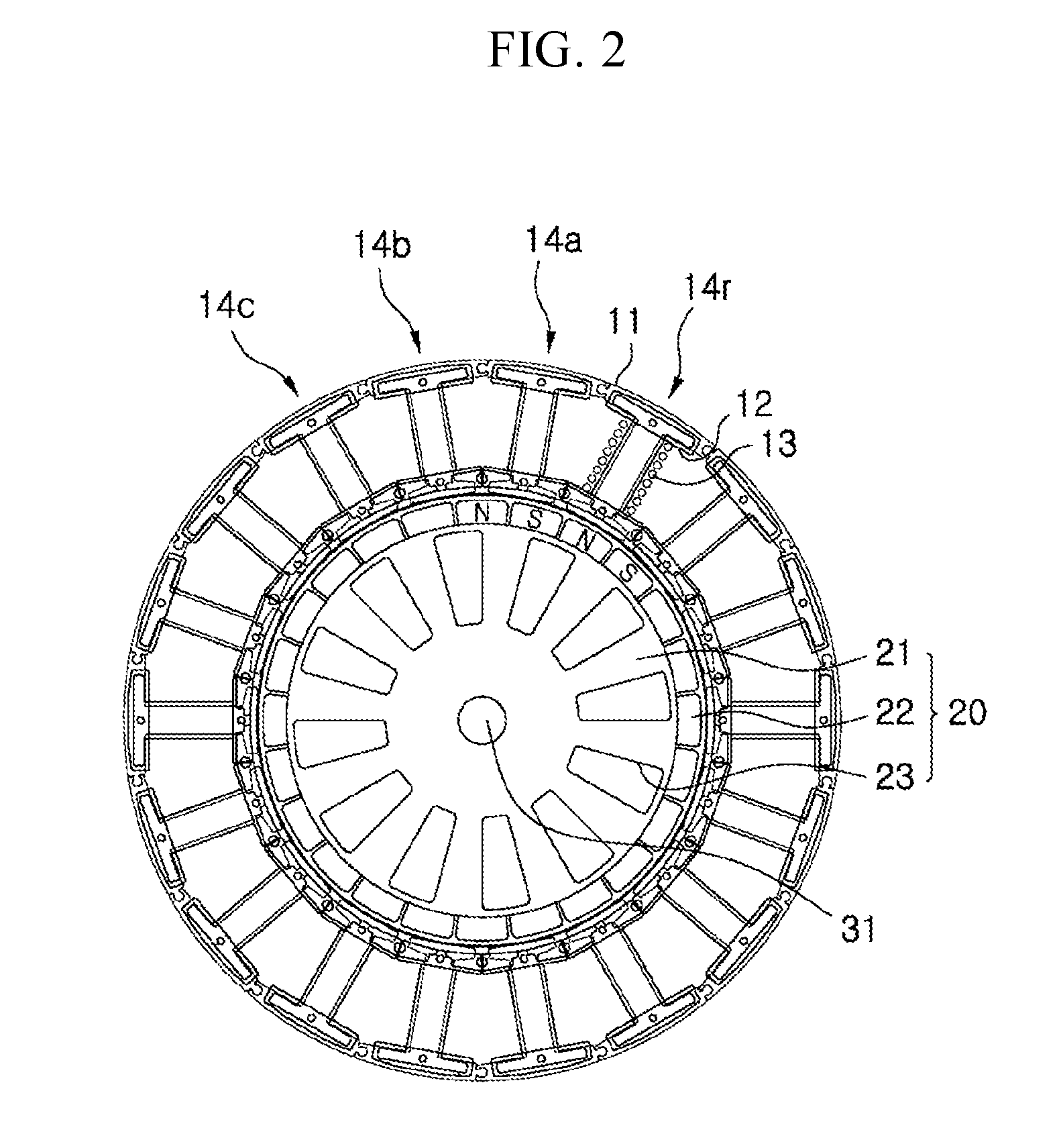
[0032]In addition, the present invention provides a high-power, high-speed electric motor that is designed to have the number of poles of a rotor that operate in a frequency band of at least 10 kHz or higher so that permeability properties of amorphous alloy materials can be used at maximum.
[0033]Further, the present invention provides an amorphous magnetic component for use in a high-power, high-speed electric motor, in which core losses may be minimized by using the magnetic component, that is, a core, made of amorphous alloy powder whose eddy current loss is decreased in a high-frequency band, and as a result, the size of the motor is minimized, so that the amorphous magnetic component may be employed in a driving system of an in-wheel motor structure.
[0034]In general, since it is difficult to mutually couple divisional cores with each other without increasing magnetoresistance in a structure of laminating silicon steel plates, it is accordingly difficult to implement an electric motor having a single-stator and single-rotor structure. However, the present invention uses a core made of amorphous alloy powder, to thereby enable the divisional cores to be closely coupled with each other, without increasing magnetoresistance. As a result, the present invention employs the divisional cores even in the single-stator and single-rotor structure, to thus promote efficiency of coil windings and minimize size and weight of the motor.

Problems solved by technology

The slotted stators cause difficult windings, require a lot of time on winding operations, and require complex and expensive coil winding equipment.
Also, a structure formed of a number of teeth induces a magnetic discontinuity, to thus affect the efficiency of a motor, and generate a cogging torque depending on the presence of slots.
In the case of a material such as an electric steel plate, the thickness of the electric steel plate is thick, to accordingly increase an iron loss, and exhibit the low efficiency in high-speed motors.
In conventional Si—Fe-based materials, a loss caused by a changing magnetic field at a frequency of about 400 Hz or more may heat the Si—Fe-based materials until the materials cannot be often cooled by even any suitable cooling devices.
Until now, it has been known that it is very difficult to provide electric devices that are easily manufactured while taking the advantages of low-loss materials, at a low-cost.
Most of attempts of applying the low-loss materials in the conventional devices have failed.
These electric devices show improved efficiency with low losses, from time to time, but may raise problems of causing a severe deterioration of the output, and big costs related to the handling such as molding of amorphous metal.
When compared with the non-oriented electric steel plates, an amorphous metal provides excellent magnetic performance, but has been considered for a long time that it is unsuitable to be used as a bulk magnetic member such as a rotor or stator for electric motors, because of certain physical properties and obstacles that occur at the time of fabrication.
For example, the amorphous metal is thinner and lighter than the non-oriented electric steel plate, and thus a fabrication tool and die will wear more rapidly.
When compared with the conventional technology such as punching or stamping, fabrication of the bulk amorphous metal magnetic member has no commercialized competitiveness due to an increase in fabrication costs for the tools and dies.
Thin amorphous metal also leads to an increase in the number of the laminates in the assembled member, and also increases the overall cost of the amorphous metal rotor or stator magnet assembly.
However, the amorphous metal is a very mild material, and thus it is very difficult to cut or mold the amorphous metal.
If the amorphous metal is annealed in order to obtain the peak magnetic characteristics, an amorphous metal ribbon is noticeably brittle.
This makes it difficult to use conventional methods to configure the bulk amorphous magnetic member, and also leads to a rise in the cost.
In addition, embrittlement of the amorphous metal ribbon may bring concerns about the durability of the bulk magnetic member in an application for an electric motor.
However, the Korean Patent Laid-open Publication No. 2002-63604 is still manufactured via a molding process such as cutting of brittle amorphous metal ribbon, and thus it is difficult to make a practical application.
Meanwhile, in the case that a high-speed motor of a high output of 100 kW and 50,000 rpm is implemented using silicon steel plates as in drive motors for electric vehicles, an eddy current increases due to high-speed rotation, and thus a problem of generating heat may occur.
Also, since the drive motors for electric vehicles are fabricated in a large size, it is not possible to apply the drive motors to the driving system of the in-wheel motor structure, and it is undesirable in terms of increasing weight of the vehicles.
In general, the amorphous strip has a low eddy current loss, but conventional motor cores that are made of laminated amorphous strips may cause it to be difficult to make a practical application due to difficulties of a manufacturing process as pointed out in the prior art, in view of the nature of the material.
In other words, the amorphous strips provides superior magnetic performance compared to non-oriented electrical steel plates, but are not applied as the bulk magnetic members such as stators or rotors for electric motors because of obstacles that occur during processing for the manufacture.

Method used


Image

  • Amorphous magnetic component, electric motor using same and method for manufacturing same
  • Amorphous magnetic component, electric motor using same and method for manufacturing same
  • Amorphous magnetic component, electric motor using same and method for manufacturing same

Examples


example 1

[0107]Amorphous alloy ribbons of a composition Fe78—Si9—B13 prepared by a melt spinning process were heat-treated at 300° C. in the air for one hour, to thus obtain preliminarily heat-treated amorphous alloy ribbons. The amorphous alloy ribbons were pulverized with a crusher, to thus obtain amorphous alloy powder, and then the amorphous alloy powder was classified into amorphous alloy powder with an average powder particle size of 20 to 50 μm, and amorphous alloy powder with an average powder particle size of 50 to 75 μm, through classification and weighing processes, to thus obtain a mixture of powder mixed at a ratio of 50% by weight of the amorphous alloy powder with an average powder particle size of 20 to 50 μm and 50% by weight of the amorphous alloy powder with an average powder particle size of 50 to 75 μm. Here, an aspect ratio of the obtained amorphous alloy powder was in the range of about 1.5 to 3.3.

[0108]Fe—Si—Al-based Sendust powder was mixed with amorphous alloy powde...

example 2

[0115]Amorphous alloy ribbons of a composition Fe735—Cu1—Nb3—Si135—B9 prepared by a melt spinning process were heat-treated at 540° C. under a nitrogen atmosphere for 40 min, to thus obtain nanocrystalline ribbons. The nanocrystalline size was in the range of 10 to 15 nm. The nanocrystalline ribbons were pulverized with a crusher to obtain nanocrystalline alloy powder, and then the nanocrystalline alloy powder was classified into nanocrystalline alloy powder with an average powder particle size of 20 to 50 μm, and nanocrystalline alloy powder with an average powder particle size of 50 to 75 μm, through classification and weighing processes, to thus obtain a mixture of powder mixed at a ratio of 50% by weight of the nanocrystalline alloy powder with an average powder particle size of 20 to 50 μm and 50% by weight of the nanocrystalline alloy powder with an average powder particle size of 50 to 75 μm. Here, an aspect ratio of the obtained nanocrystalline alloy powder was in the range ...


PUM

PropertyMeasurementUnit
aspect ratioaaaaaaaaaa
frequencyaaaaaaaaaa

Abstract

An amorphous magnetic component for use in a high-power, high-speed electric motor, in which amorphous metal materials are powdered, compressed, and molded, to be easily molded into magnetic components of a complex shape, and crystalline metal powder of excellent soft magnetic properties is added to the amorphous alloy powder, to promote improvement of a magnetic permeability and improvement of a packing density at the time of compression molding. A method of manufacturing the amorphous magnetic component; includes the steps of: pulverizing ribbons or strips of amorphous alloys to obtain plate-shaped amorphous alloy powder; classifying the amorphous alloy powder, and mixing the amorphous alloy powder with spherical soft magnetic powder, in order to improve magnetic permeability and packing density, to obtain mixed powder; mixing the mixed powder with a binder, to be molded into a shape of the magnetic components; and sintering the molded magnetic components to implement magnetic properties.

Description

TECHNICAL FIELD[0001]The present invention relates to an amorphous magnetic component, an electric motor using the amorphous magnetic component, and a method of manufacturing the amorphous magnetic component, and more specifically, to an amorphous magnetic component for use in a high-power, high-speed electric motor, in which amorphous metal materials are powdered, compressed, and molded, to thus be easily molded into magnetic components of a complex shape, and crystalline metal powder of excellent soft magnetic properties is added to the amorphous alloy powder, to thus promote improvement of a magnetic permeability and improvement of a packing density at the time of compression molding, and a method of manufacturing the amorphous magnetic component.[0002]In addition, the present invention relates to a high-power, high-speed electric motor having the number of poles that operate in a frequency band of at least 10 kHz or higher so that permeability properties of amorphous alloy mater...

Claims


Application Information

Patent Timeline
Patent Type & Authority Applications(United States)
IPC IPC(8): H01F1/153H02K1/02H01F41/02
CPCB22F2998/10C22C2200/02H02K1/02H01F1/15333H01F1/15375H01F1/26H01F41/0246H01F1/153H01F41/02H01F3/08C22C2202/02C22C33/02B22F2009/048B22F1/0059B22F3/02B22F3/10B22F1/08B22F1/10H01F1/22H01F1/38B22F9/08H02K1/27
Inventor KIM, BYOUNG SOO
Owner AMOTECH
Why Eureka
Try Eureka