
Combined peak reduction equalizer and phase/amplitude pre-distortion

a technology of equalizer and phase/amplitude, applied in the field of combined peak reduction equalizer filter and phase/amplitude predistortion, can solve the problems of higher power consumption, cost and size of the system, higher power consumption, cost and size, etc., and achieve the effect of boosting the power handling of the transmitter sub-system and improving the signal handling of any wireless signal

Inactive Publication Date: 2010-08-31
ALTERA CORP
View PDF8 Cites 32 Cited by
  • Summary
  • Abstract
  • Description
  • Claims
  • Application Information

AI Technical Summary

Benefits of technology

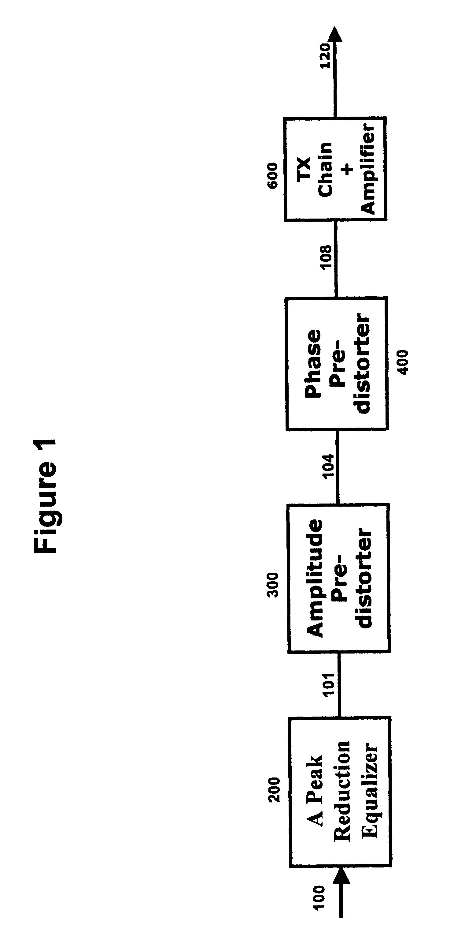
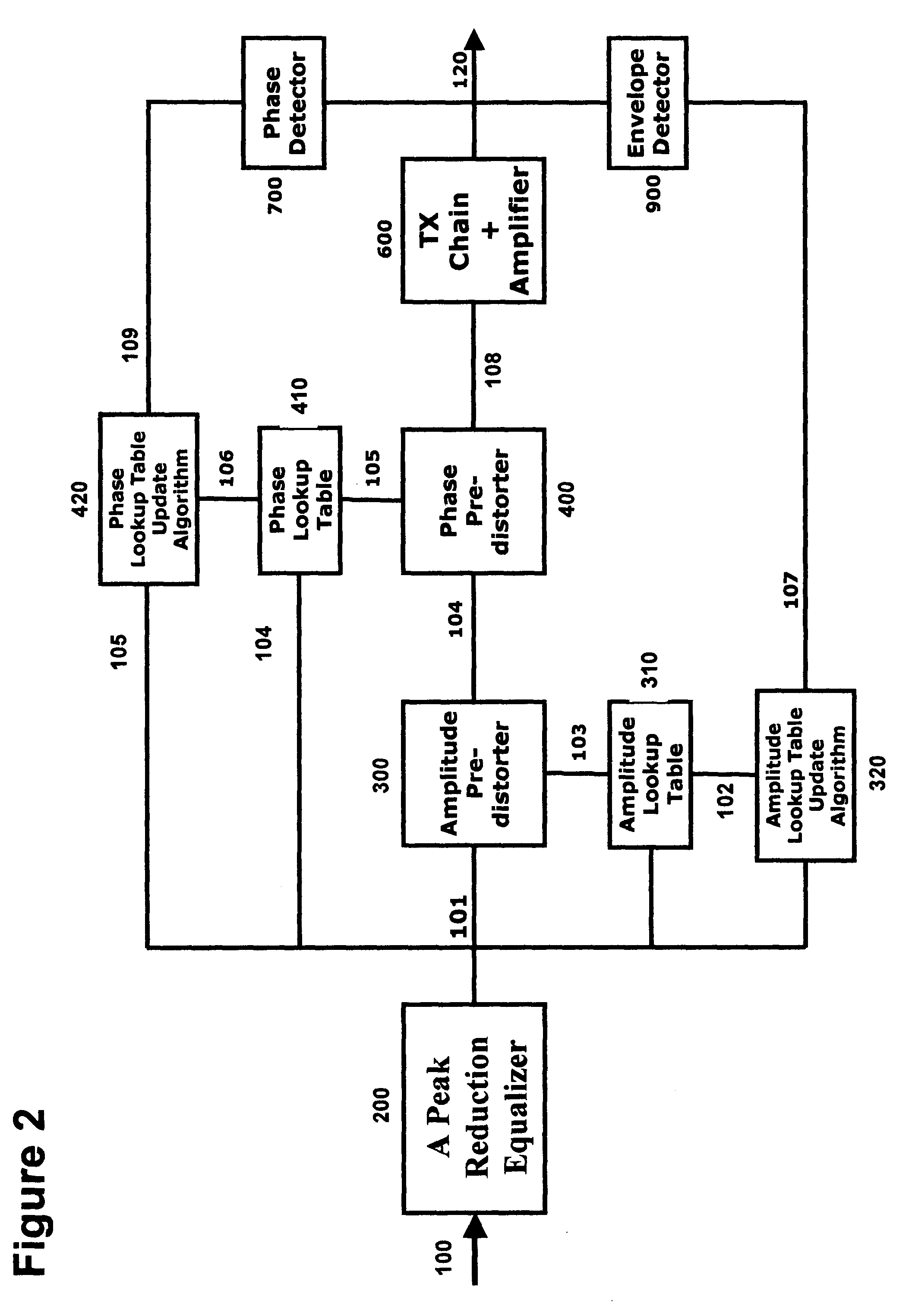
[0002]According to the invention, a combined peak reduction equalizer filter and phase / amplitude pre-distortion, for use with OFDM and OFDMA communication transmitter sub-system, uses a plurality of simple and accurate algorithm in conjunction with intelligent signal processing to improve signal handling of any wireless, optical, or wireline communication transmitter. By intelligent, it is meant that the algorithm has features of maintaining the signal emission and quality requirements while applying the combined peak reduction equalizer filter and phase / amplitude pre-distortion. The combined peak reduction equalizer filter and phase / amplitude pre-distortion uses the transmitter sub-system input which is a baseband signal as its input and conditions, smoothens and pre-distorts the signal before applying it back to the transmitter sub-system. The conditioning, smoothening and pre-distortion helps to boost the power handling of the transmitter sub-system or acts more linearly.

Problems solved by technology

This sub-system has a major contribution in cost, power consumption, and size of the system.
The higher the linearity, the higher the power consumption, cost and size.

Method used


Image

  • Combined peak reduction equalizer and phase/amplitude pre-distortion
  • Combined peak reduction equalizer and phase/amplitude pre-distortion
  • Combined peak reduction equalizer and phase/amplitude pre-distortion

Examples


Embodiment Construction

[0013]In a first preferred embodiment of the invention, a peak reduction equalizer filter uses digital baseband signal. In a second preferred embodiment the main baseband signal is amplitude conditioned and smoothened using a peak reduction equalizer filter with a dynamically configurable weighting mask. In a third embodiment a peak reduction equalizer filter injects in band and out of band signal into the main baseband signal through a feedforward loop. In a fourth embodiment the injected in band and out of band signal into the main baseband signal is adjusted by a dynamically configurable weighting mask in a feedforward loop. In a fifth embodiment the equalizer filter in a feedforward loop uses Discrete Fourier Transform and Inverse Discrete Fourier Transform DFT / IDFT. In a sixth embodiment a dynamically configurable MASK gets its input from a MASK updating algorithm. In a seventh embodiment a MASK updating algorithm gets its input from an OFDM or OFDMA physical layer PHY, Median ...


PUM


Abstract

A technique for a combined peak reduction equalizer filter and phase / amplitude pre-distortion is described. The input to a transmitter chain is modified by a combined equalizer filter and pre-distorter, prior to being applied to the transmitter chain. The equalizer filter modifies and smoothen the amplitude of the signal followed by pre-distorter to compensate for phase and amplitude distortion from transmitter chain or power amplifier. The modified and smoothen signal has its peaks reduced before being pre-distorted. The baseband signal pre-distortion results in cancellation of the distortion being introduced by the power amplifier or the transmitter chain. The amplitude pre-distortion is applied to the amplitude of the peak reduced baseband signal using the envelope information from the output of the transmitter chain or power amplifier and the phase pre-distortion is applied to the phase of the peak reduced baseband signal using the differential phase information between input and output of the power amplifier or the transmitter chain.

Description

BACKGROUND OF INVENTION[0001]The present invention relates to a combined peak reduction equalizer filter and phase / amplitude pre-distortion to boost the performance of any Orthogonal Frequency Division Multiplexing (OFDM) and Orthogonal Frequency Division Multiple Access (OFDMA) communication transmitter. In any OFDM and OFDMA communication system one of the critical sub-systems is the transmitter. This sub-system has a major contribution in cost, power consumption, and size of the system. The main reason is the requirement of communication transmitter sub-system for linear components. The higher the linearity, the higher the power consumption, cost and size. In order to minimize the cost, size and power consumption there is a need for techniques that overcome this problem. This invention conquers these challenges by using a simple and accurate combined peak reduction equalizer filter and phase / amplitude pre-distortion module used at the input to this sub-system.SUMMARY OF INVENTION...

Claims


Application Information

Patent Timeline
IPC IPC(8): H04K1/02
CPCH04L25/03343H04L27/2614
Inventor ANVARI, KIOMARS
Owner ALTERA CORP
Learn More