
Low emissions combustion apparatus and method

a combustion apparatus and low emission technology, applied in the field of apparatus and methods of combustion, can solve the problems of simultaneous undesired increases in co and uhc emissions, increased cost and complexity of controlling overall emissions, and increased co emissions with incremental increases. achieve the effect of stable combustion

Active Publication Date: 2010-09-07
VAST HLDG LLC
View PDF18 Cites 79 Cited by
  • Summary
  • Abstract
  • Description
  • Claims
  • Application Information

AI Technical Summary

Benefits of technology

"The present invention relates to a method and system for controlling the combustion of carbonaceous fuels using a primary combustion region and equilibration regions to reduce emissions of nitrogen oxides (NOx) and other pollutants. The method involves the delivery of fluid to the combustion chamber in a controlled and staged manner, using a progressive combustion approach. The system includes a combustor design that optimizes stability and control of peak temperatures, while reducing CO and UHC concentrations. The use of equilibration regions downstream of the primary combustion region further reduces CO emissions. The method and system can be used in various combustion systems, such as gas turbines, and can help achieve low NOx emissions levels."

Problems solved by technology

In typical combustion systems, control measures aimed at controlling each of NOx, CO and UHCs can be counterproductive, thus increasing the cost and complexity of controlling overall emissions.
Consequently, diluent-based NOx reduction strategies typically result in simultaneous undesired increases in the CO and UHC emissions in the energetic or working fluid leaving the combustor, and vice versa.
Furthermore while higher temperatures seem to promote UHC removal, CO emissions tend to increase with incremental increases in temperature in high temperature ranges.
This is especially a problem as higher turbine inlet temperatures are sought for higher efficiency in gas turbine systems.
Efforts to increase system throughput typically result in shorter hot residence times, further raising UHC and CO concentrations.
Rapid expansion through a work engine or expander such as a turbine typically results in rapid reductions in fluid temperature that “freeze” or “quench” the conversion of UHC and CO to CO2, which can result in high UHC and CO emissions.
As in-situ methods typically have limited success in reducing emissions, they are often combined with add-on technologies that reduce or remove pollutant species produced and present in the combustion product gases, e.g. selective catalytic reduction (SCR).
The utilized add-on technologies often substantially increase the volume, footprint and cost of the systems because of the high specific volume and comparatively long kinetic time-scales of reactions that characterize exhaust gases.
Thus, even though these methods may successfully reduce emissions to acceptable levels, they often substantially increase equipment, operation and maintenance costs.

Method used


Image

  • Low emissions combustion apparatus and method
  • Low emissions combustion apparatus and method
  • Low emissions combustion apparatus and method

Examples


Embodiment Construction

[0044]U.S. Pat. Nos. 3,651,641, 5,617,719, 5,743,080 and 6,289,666 to Ginter are hereby expressly incorporated by reference herein. These teach diluted combustion methods utilizing delivery of thermal diluent (such as water) into a combustor to cool the combustion, reducing the use of excess dilution air. This invention further expressly incorporates by reference herein the following US patent applications by Hagen et al.:

[0045]20050056313 Method and apparatus for mixing fluids of Mar. 17, 2005

[0046]20040244382 Distributed direct fluid contactor of Dec. 9, 2004

[0047]20040238654 Thermodynamic cycles using thermal diluent of Dec. 2, 2004 and

[0048]20040219079 Trifluid reactor of Nov. 4, 2004. These applications teach further methods of delivering aqueous diluent with improved control over transverse temperature profiles.

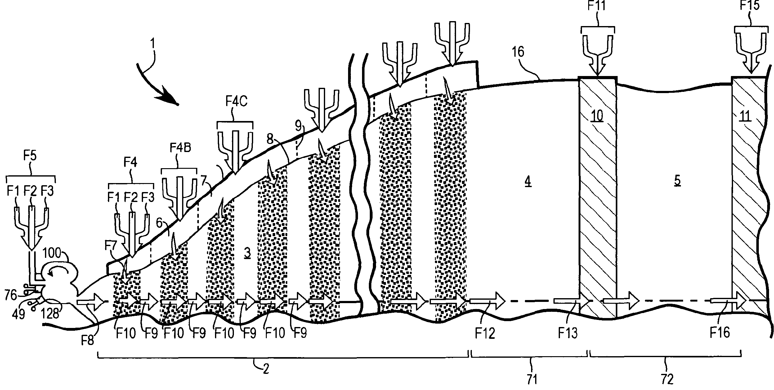
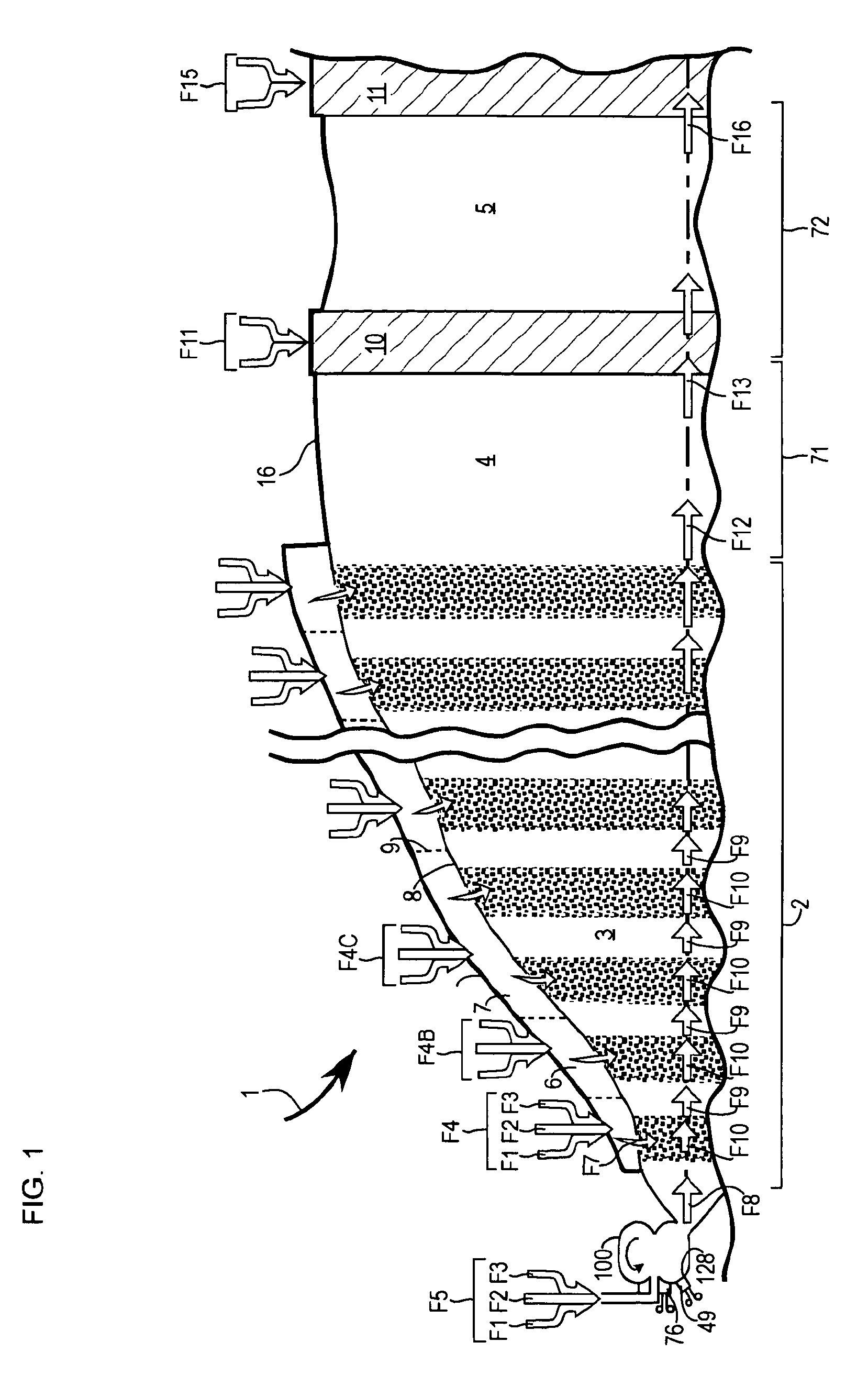
[0049]FIG. 1 is a generalized representative embodiment of a combustor apparatus utilizing the Progressive Combustion and Equilibration methods to control emissions. Th...


PUM


Abstract

Clean combustion and equilibration equipment and methods are provided to progressively deliver, combust and equilibrate mixtures of fuel, oxidant and aqueous diluent in a plurality of combustion regions and in one or more equilibration regions to further progress oxidation of products of incomplete combustion, in a manner that sustains combustion while controlling temperatures and residence times sufficiently to reduce CO and NOx emissions to below 25 ppmvd, and preferably to below 3 ppmvd at 15% O2.

Description

CROSS-REFERENCE TO RELATED APPLICATIONS[0001]This application claims the benefit of U.S. Provisional App. 60 / 590,073, filed Jul. 21, 2004 and U.S. Provisional App. 60 / 579,135, filed Jun. 11, 2004.BACKGROUND OF THE INVENTION[0002]1. Field of the Invention[0003]This invention relates to an apparatus and method of combustion that produces low emissions, carbon monoxide and oxides of nitrogen in particular, and to progressing reactions to produce low intermediate products and byproducts.[0004]2. Description of the Related Art[0005]Energy conversion and chemical processing industries, seek to economically remove and / or produce specific chemical species. Unburned hydrocarbons (UHCs), carbon monoxide (CO), and oxides of nitrogen (NOx) are three sets of chemical species which are commonly found in energetic fluids formed in hot chemical reactions, and more particularly, in combustion-based energy conversion industries.[0006]Legislative authorities have periodically reduced allowable emissio...

Claims


Application Information

Patent Timeline
Patent Type & Authority Patents(United States)
IPC IPC(8): F02C3/20F23C5/00F23R3/34F02C3/30F23C7/00F23C6/04F23L7/00
CPCF02C6/00F23C6/047F23D14/02F23D14/66F23L7/002F23R3/346F23L7/00F23D2900/00014F23L2900/07002F23L2900/07008Y02E20/344Y02E20/34
Inventor CAMPBELL, PAUL ANDREWHAGEN, DAVID
Owner VAST HLDG LLC
Learn More