Cellular reflectarray antenna and method of making same

a reflector array and antenna technology, applied in the field of reflector arrays, to achieve the effect of convenient and quick installation

Inactive Publication Date: 2010-09-07
NASA
View PDF17 Cites 40 Cited by
  • Summary
  • Abstract
  • Description
  • Claims
  • Application Information

AI Technical Summary

Benefits of technology

[0024]It is an object of the present invention to provide a bidirectional dual broadband television and internet reflectarray which is: unobtrusive in use, easily and quickly installed through simple orientation due north and parallel to the earth, inexpensive, and not removable from the cell in which it is originally installed.

Problems solved by technology

Undesirable scattered energy from the ground plane at boresight was nearly as prominent as the desired beams (at ±30°) because of the non-optimal selection of a dielectric constant.

Method used


Image

  • Cellular reflectarray antenna and method of making same
  • Cellular reflectarray antenna and method of making same
  • Cellular reflectarray antenna and method of making same

Examples


Embodiment Construction

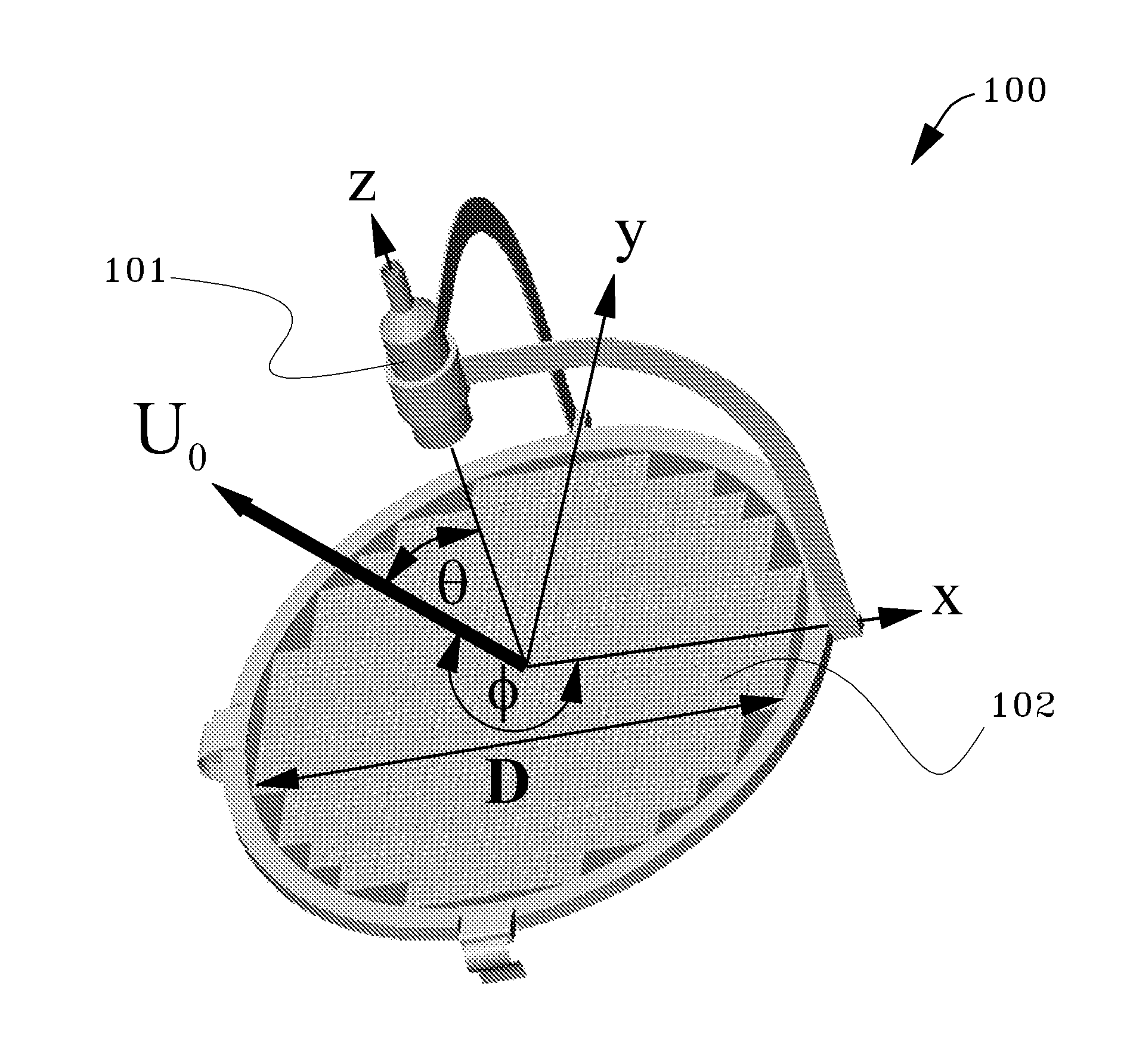
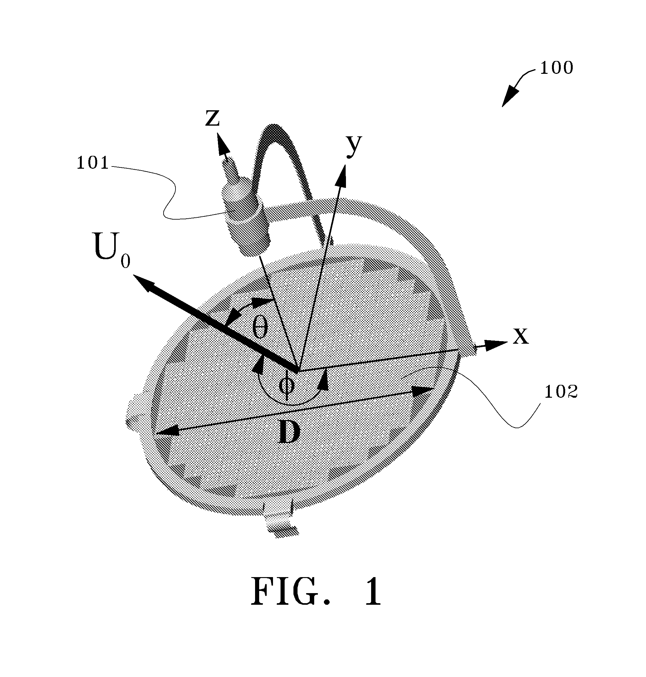
[0044]The cellular reflectarray antenna is intended to replace conventional parabolic reflectors that must be physically aligned to a particular satellite in geostationary orbit. Specifically, the cellular reflectarray antenna is designed for a certain geographic location defined by latitude and longitude that is called a “cell”. A particular cell may occupy approximately 1,500 square miles. Other cell sizes are specifically contemplated herein and may be necessary for high±latitudes. The cellular reflectarray antenna designed for a particular cell is simply positioned such that an index aligns to magnetic North and the antenna surface is level (parallel to the level ground). A given cellular reflectarray antenna will not operate in any other cell because the delay lines for the individual elements are specific to that cell.

[0045]The specific design and fabrication of the reflectarrray for a specific latitude and longitude (i.e. a zip code) inherently prevents pirating dish receiver...


PUM


Abstract

A method of manufacturing a cellular reflectarray antenna arranged in an m by n matrix of radiating elements for communication with a satellite includes steps of determining a delay φm,n for each of said m by n matrix of elements of said cellular reflectarray antenna using sub-steps of: determining the longitude and latitude of operation, determining elevation and azimuth angles of the reflectarray with respect to the satellite and converting theta0 0) and phi0 0), determining Δβm,n, the pointing vector correction, for a given inter-element spacing and wavelength, determining Δφm,n, the spherical wave front correction factor, for a given radius from the central element and/or from measured data from the feed horn; and, determining a delay φm,n for each of said m by n matrix of elements as a function of Δβm,n and Δφm,n..

Description

ORIGIN OF THE INVENTION[0001]The invention described herein was made by an employee of the United States Government, and may be manufactured and used by the government for government purposes without the payment of any royalties therein and therefor.FIELD OF THE INVENTION[0002]The field of the invention is in antennas and, in particular, in the field of reflectarray antennas used for communication with earth-orbiting satellites.BACKGROUND OF THE INVENTION[0003]The reflectarray is an alternative to directly-radiating phased array antennas and promises higher efficiency at reduced cost. A key advantage of reflectarray antennas over conventional phased arrays is elimination of the complex beam-forming manifold and costly transmit / receive modules. The reflectarray is also reciprocal—the same aperture can be used for transmit and receive functions. In 1963, Berry, Malech and Kennedy introduced this new class of antennas that utilized an array of elementary antennas as a reflecting surfac...

Claims


Application Information

Patent Timeline
Patent Type & Authority Patents(United States)
IPC IPC(8): H01Q19/06H01Q19/10H01Q1/38
CPCH01Q3/46H01Q15/148
Inventor ROMANOFSKY, ROBERT R
Owner NASA
Why Eureka
Try Eureka