Side feed/centre ash dump system

a biomass energy recovery system and dump system technology, applied in the direction of gasification process details, combustion process, combustible gas production, etc., can solve the problems of high capital cost, difficult fuel delivery and ash removal from the gasifier primary chamber, and impede the use of small or even medium-sized biomass energy recovery systems. achieve clean and efficient energy recovery, low capital cost of the apparatus, and cost-effective

Active Publication Date: 2010-09-14
KENNETH DAVISON
View PDF61 Cites 16 Cited by
  • Summary
  • Abstract
  • Description
  • Claims
  • Application Information

AI Technical Summary

Benefits of technology

[0006]The apparatus further includes means for storing the solid organic materials; transfer passage means connecting the means for storing with the inlet opening for transferring the solid fuel from the means for storing through the inlet opening into the primary oxidation chamber to form a fuel bed of solid fuel including the organic material in the primary oxidation chamber. A means for supplying an oxidant into the primary oxidation chamber supplies a first oxidant to gasify the solid organic materials to produce gasified organic materials including a first gaseous effluent, and thereby leaving a residue. The means for supplying the oxidant may have a plurality of air distribution members extending across said bottom portion and adjacent to fuel driven into said bed through the inlet opening of the primary oxidation chamber so as to introduce air into the interior of the fuel bed to thereby promote evenly distributed gasification, evenly distributed through said fuel bed.
[0023]More particularly, the present invention provides an improved method apparatus for efficiently producing energy at relatively low rates by the gasification of organic materials.

Problems solved by technology

On many conventional gasification systems there has been difficulty in fuel delivery and ash removal from the gasifier primary chambers.
However, the higher capital cost which has heretofore been associated with biomass energy recovery systems has precluded their successful use in small or even medium size energy recovery systems.
However, it is not known that any of the inventions described in these patents have been successfully adapted to recovering biomass energy on a cost-effective basis in small and medium size energy recovery system.
Dealing with high ash fuels has proved especially difficult for many of these processes.

Method used


Image

  • Side feed/centre ash dump system
  • Side feed/centre ash dump system
  • Side feed/centre ash dump system

Examples


Embodiment Construction

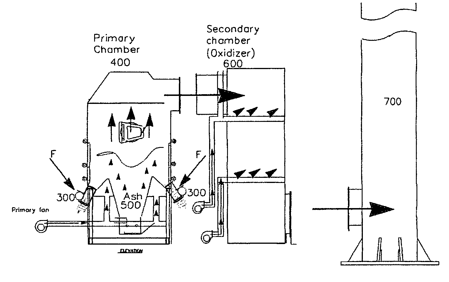
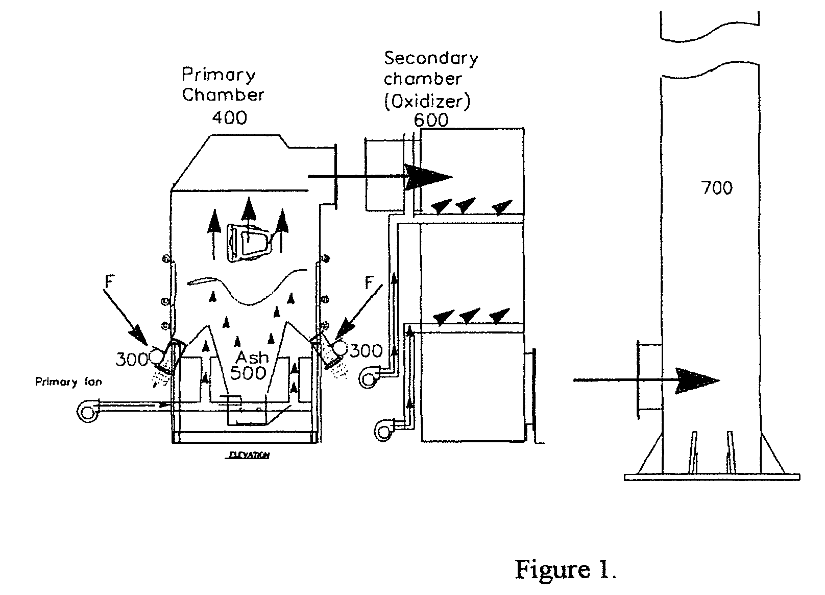
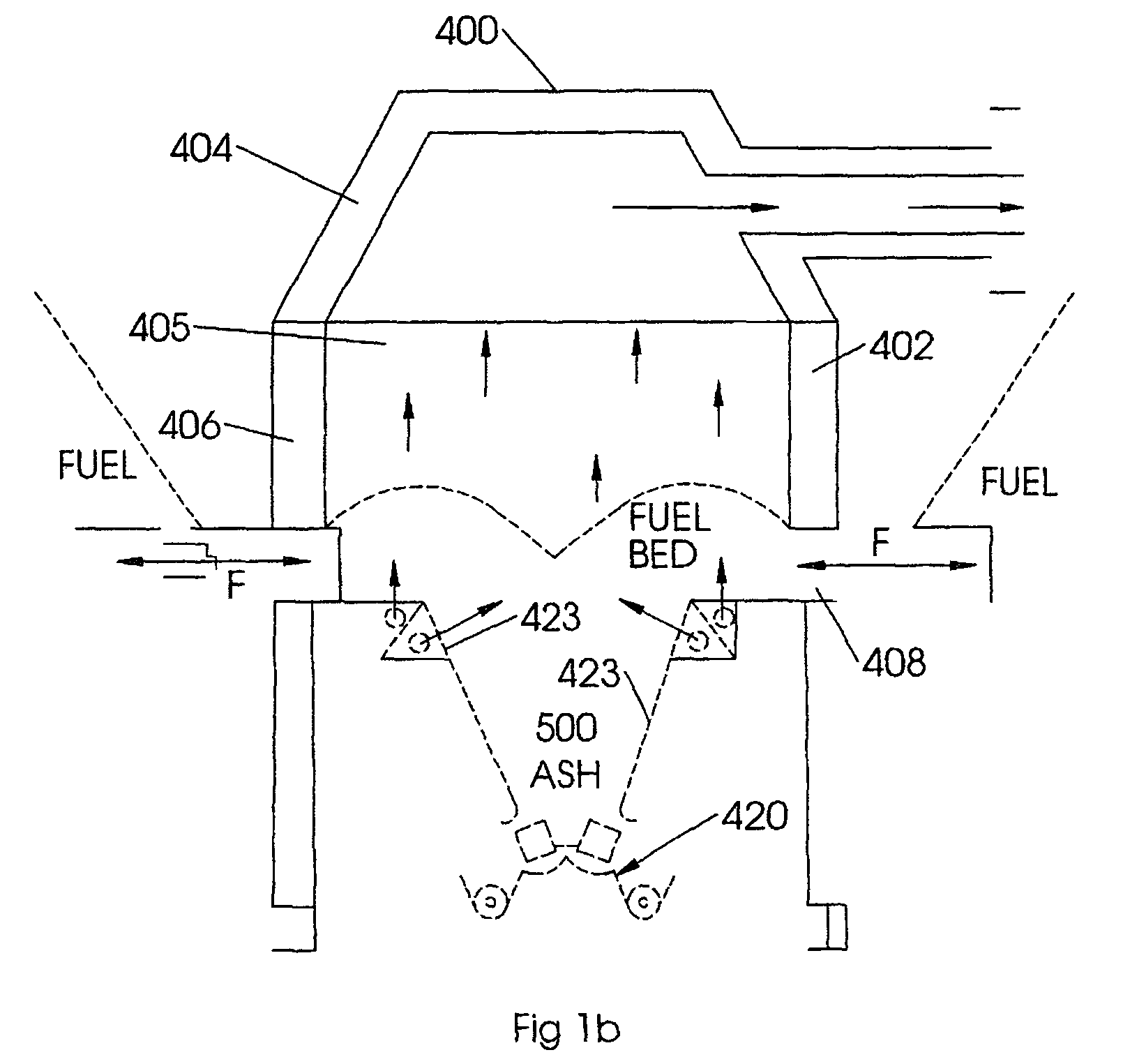
[0055]As is shown in FIG. 1, an apparatus for practicing the present invention utilizes a feed assembly, indicated generally by reference numeral 300, which is driven by a drive assembly and which feeds material from a storage hopper assembly 100 into a primary oxidation chamber 400. The inert or unburned portion of the feed material or fuel fed into primary oxidation chamber 400 is withdrawn as ash 500 and transported from chamber 400 by an ash removal system 420. In the preferred embodiment of the invention, the fuel fed into the primary oxidation chamber 400 is only partially oxidized therein, and hence there is provided a secondary oxidation chamber, indicated generally by reference numeral 600, to complete the oxidation of the partially oxidized gaseous effluent from chamber 400 after it leaves primary oxidation chamber 400. The fully oxidized gaseous effluent from secondary oxidation chamber 600 may be used as a source of heat energy in a device or process which requires heat ...


PUM


Abstract

An apparatus for gasifying solid organic fuel includes a refractory-lined oxidation chamber, fuel storage, a transfer connecting the fuel storage with an inlet into the oxidation chamber for transferring in an upwardly inclined direction the solid fuel from the fuel storage into the inlet to form an upwardly mounded fuel bed. An oxidant is supplied into the fuel bed to gasify the organic materials in the fuel to produce a gaseous effluent from the fuel bed, thereby leaving a residue of the fuel. The residue drops through an opening under the oxidation chamber onto a residue removal transfer. The oxidant is supplied through a plurality of perforated air distribution members extending across the fuel bed cavity in the oxidation chamber so as to introduce air into the interior of the fuel bed to thereby promote evenly distributed gasification, evenly distributed through the fuel bed.

Description

CROSS REFERENCE TO RELATED APPLICATION[0001]This application claims priority from U.S. Provisional Patent Application No. 60 / 629,972 filed Nov. 23, 2004 entitled Side Feed / Centre Ash Dump System.FIELD OF THE INVENTION[0002]This invention relates to a method and apparatus for gasifying solid organic materials to convert the chemical energy stored in such materials to thermal energy. More particularly, this invention relates to a method and apparatus for gasifying low or high ash biomass materials. The high temperature gases produced by the practice of the invention can be utilized to advantage, for example, as the thermal energy source for conventional heat exchange equipment such as boilers.BACKGROUND OF THE INVENTION[0003]On many conventional gasification systems there has been difficulty in fuel delivery and ash removal from the gasifier primary chambers. This has been especially apparent on high ash fuels as well as fuels with low ash melting or fusion temperatures.[0004]It has b...

Claims


Application Information

Patent Timeline
Patent Type & Authority Patents(United States)
IPC IPC(8): F23G5/12
CPCC10J3/22C10J3/34C10J3/36F23B90/06F23G5/0276F23G5/46F23G7/10C10J2200/09C10J2200/15C10J2200/152C10J2200/158C10J2300/0916C10J2300/0946C10J2300/0956C10J2300/0959C10J2300/1876F23G2201/303
Inventor DAVISON, KENNETHSTROULGER, NEAL
Owner KENNETH DAVISON
Why Eureka
Try Eureka