Synthesis of carbon nanotubes by selectively heating catalyst

a catalyst and selective heating technology, applied in the direction of crystal growth process, polycrystalline material growth, chemically reactive gas, etc., can solve the problems of high negative bias formation of wafers and device integration problems

Active Publication Date: 2010-09-14
CFD RES CORP
View PDF5 Cites 28 Cited by
  • Summary
  • Abstract
  • Description
  • Claims
  • Application Information

AI Technical Summary

Problems solved by technology

A disadvantage of DC systems is the formation of high negative bias on the wafer in these systems (>300 V).
This heating often damages the substrate or causes device integration problems (3-5).

Method used


Image

  • Synthesis of carbon nanotubes by selectively heating catalyst
  • Synthesis of carbon nanotubes by selectively heating catalyst
  • Synthesis of carbon nanotubes by selectively heating catalyst

Examples


example

Selective Heating of Catalyst Using a RF Source

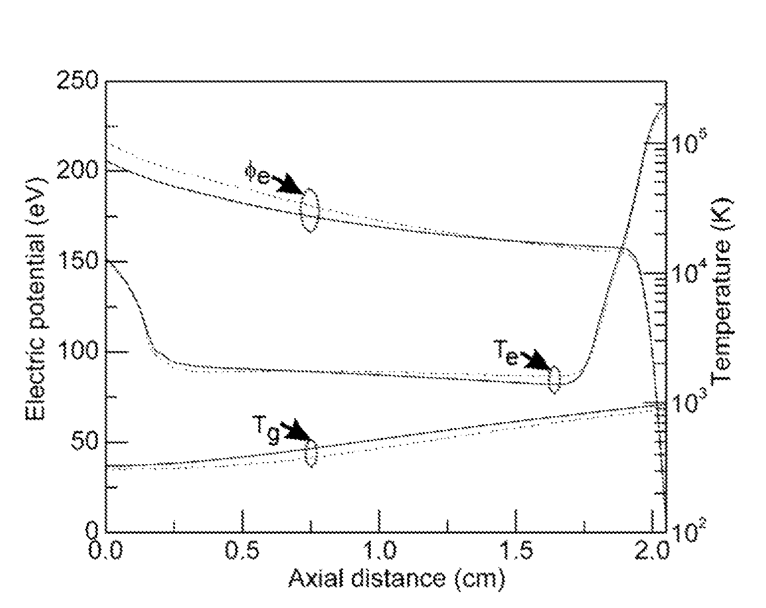
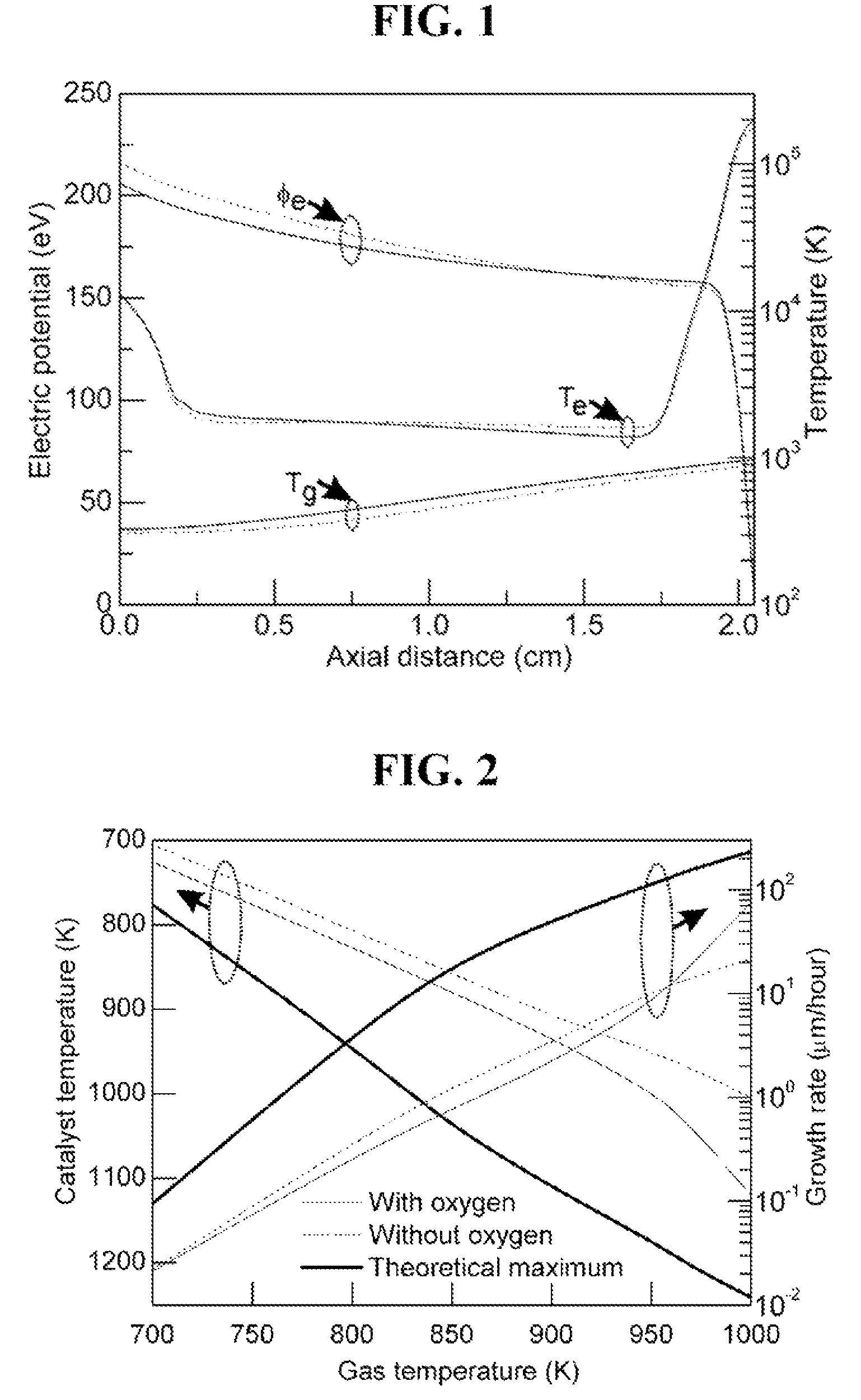
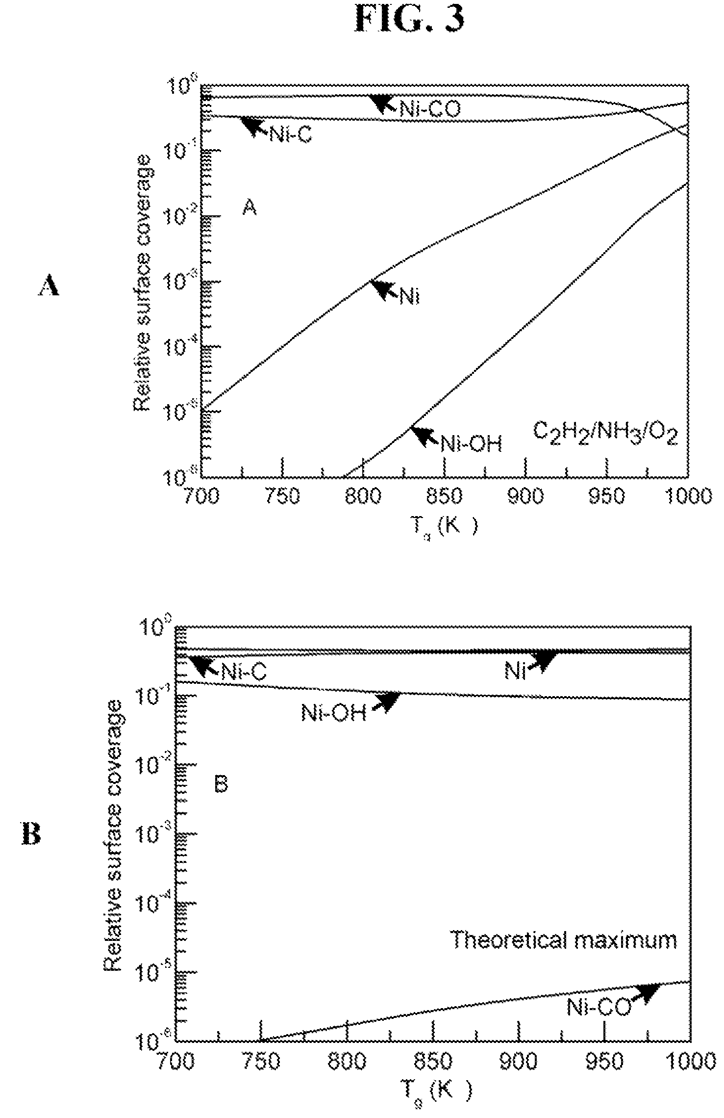
[0040]Low-temperature growth of vertically aligned CNT (VACNT) may be performed in a mixture of acetylene and ammonia gas at several Ton: of total pressure flowing at around 60 and 80 sccm respectively, 700° C., and a bias of 500 V between substrate and a showerhead anode that maintains a current of 200 mA. An example of a system for low-temperature synthesis of CNT is shown in FIG. 6, The system comprises a 13.56 MHz RF source 1 for creating plasma discharge and an additional pulsed RF power source 2 with tunable frequency in the GHz range for inductively heating catalytic nanoparticles. A nonconducting substrate 3 is used to eliminate substrate Joule heating and a cooling system 4 is used for active cooling of the substrate. The system is initially evacuated to approximately 10−6 Torr using, for example, coupled turbo and mechanical pumps 5 so that the chamber 6 can be evacuated first mechanically and then using the turbo pump. To mai...


PUM

PropertyMeasurementUnit
temperaturesaaaaaaaaaa
sizeaaaaaaaaaa

Abstract

The present invention is a catalytic chemical vapor deposition method and apparatus for synthesizing carbon nanotubes and / or carbon nanofibers (CNTs) on a substrate by selectively heating a catalyst for CNT synthesis on or near the surface of the substrate. Selective heating of the catalyst is achieved using an exothermic oxidation reaction on the surface of the catalyst. Selective heating of the catalyst prevents heating of the substrate and enables the synthesis of CNTs on temperature sensitive substrates.

Description

STATEMENT REGARDING FEDERALLY SPONSORED RESEARCH OR DEVELOPMENT[0001]The U.S. Government may have certain rights in this invention pursuant to SBIR Contract OII-0611099 awarded by the National Science Foundation.CROSS-REFERENCE TO RELATED APPLICATIONS[0002]Not ApplicableINCORPORATED-BY-REFERENCE OF MATERIAL SUBMITTED ON A COMPACT DISC[0003]Not ApplicableBACKGROUND OF THE INVENTION[0004]1. Field of the Invention[0005]The present invention pertains to the synthesis of carbon nanotubes by catalytic chemical vapor deposition methods. Specifically, the present invention involves methods and apparatus, for making carbon nanotubes comprising the selective heating of catalysts and their products.[0006]2. Description of Related Art[0007]Carbon nanotubes (CNTs) are graphitic filaments / whiskers with diameters ranging from 0.4 to 500 nm and lengths in the range of several micrometers to millimeters. The designation “CNT” is often used to call all types of vertically aligned carbon tabular struc...

Claims


Application Information

Patent Timeline
Patent Type & Authority Patents(United States)
IPC IPC(8): C23C16/00C23C4/00
CPCB82Y30/00C23C16/0281C23C16/26C23C16/503C30B25/10C30B25/18C30B29/602Y10S977/742
Inventor VASENKOV, ALEKSEY V.
Owner CFD RES CORP
Why Eureka
Try Eureka