
Long range active thermal imaging system and method

a thermal imaging and long-range technology, applied in radiation thermography, optical radiation measurement, instruments, etc., can solve the problems of large amount of energy required on target to produce measurable signatures, prohibitive large antenna size required for conventional long-wavelength microwave systems with long standoff distances, and severe limitation of radar systems resolution

Inactive Publication Date: 2010-09-14
THE UNITED STATES OF AMERICA AS REPRESENTED BY THE SECRETARY OF THE NAVY
View PDF13 Cites 32 Cited by
  • Summary
  • Abstract
  • Description
  • Claims
  • Application Information

AI Technical Summary

Benefits of technology

[0011]The present invention provides a method for heating an area with electromagnetic radiation at a substantial distance from the source of that radiation. Objects or features within the irradiated area are heated at different rates due to differences in electromagnetic absorption and thermal properties. These small temperature differences are detected with an infrared imaging device. This makes it possible to identify objects or examine features that would not otherwise be apparent.
[0022](8) The radiation penetrates into nonmetallic objects, which makes it easier to produce a thermal signature from subsurface features or objects. Optical or laser heating sources for active thermal imaging generally involve only heating of the surface.

Problems solved by technology

In comparison, the antenna size required for conventional long wavelength microwave systems with long standoff distances is prohibitive large, and such systems have only been used for very short range applications.(3) The required energy on target to produce a measurable signature is relatively modest.
Resolution can be a severe limitation for radar systems, even at high frequencies.(5) If the source is sufficiently powerful, the system has the potential for rapid scanning rates (>10 m2 / s) at standoff distances of hundreds of meters.
This is a common feature of active techniques but is often not useful for passive thermal imaging because the temperature changes are so slow.(10) With appropriate focusing optics and beam power, the intensity and dwell time on target can be increased to the point where the target is damaged or destroyed.

Method used


Image

  • Long range active thermal imaging system and method
  • Long range active thermal imaging system and method
  • Long range active thermal imaging system and method

Examples


Embodiment Construction

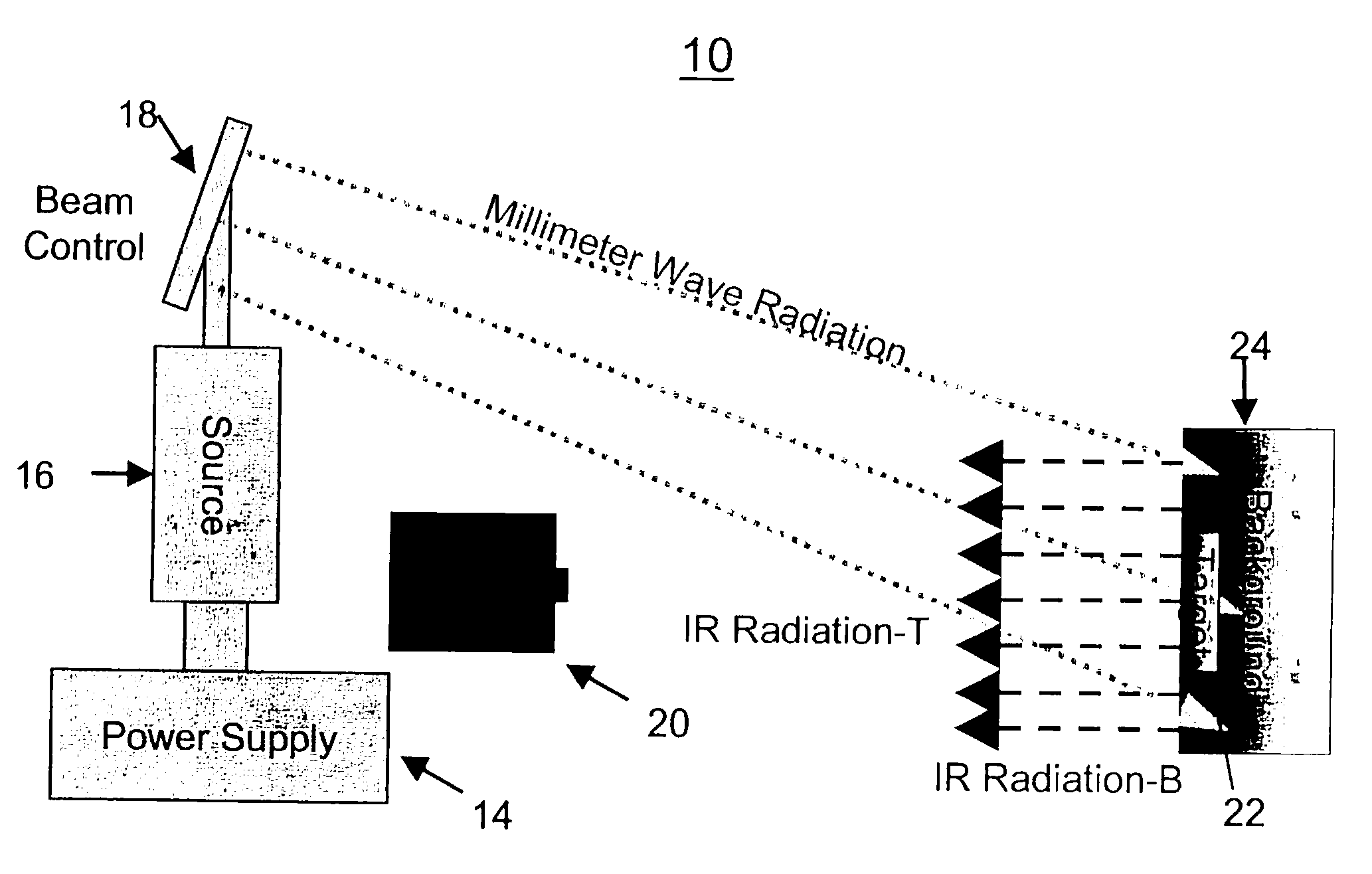
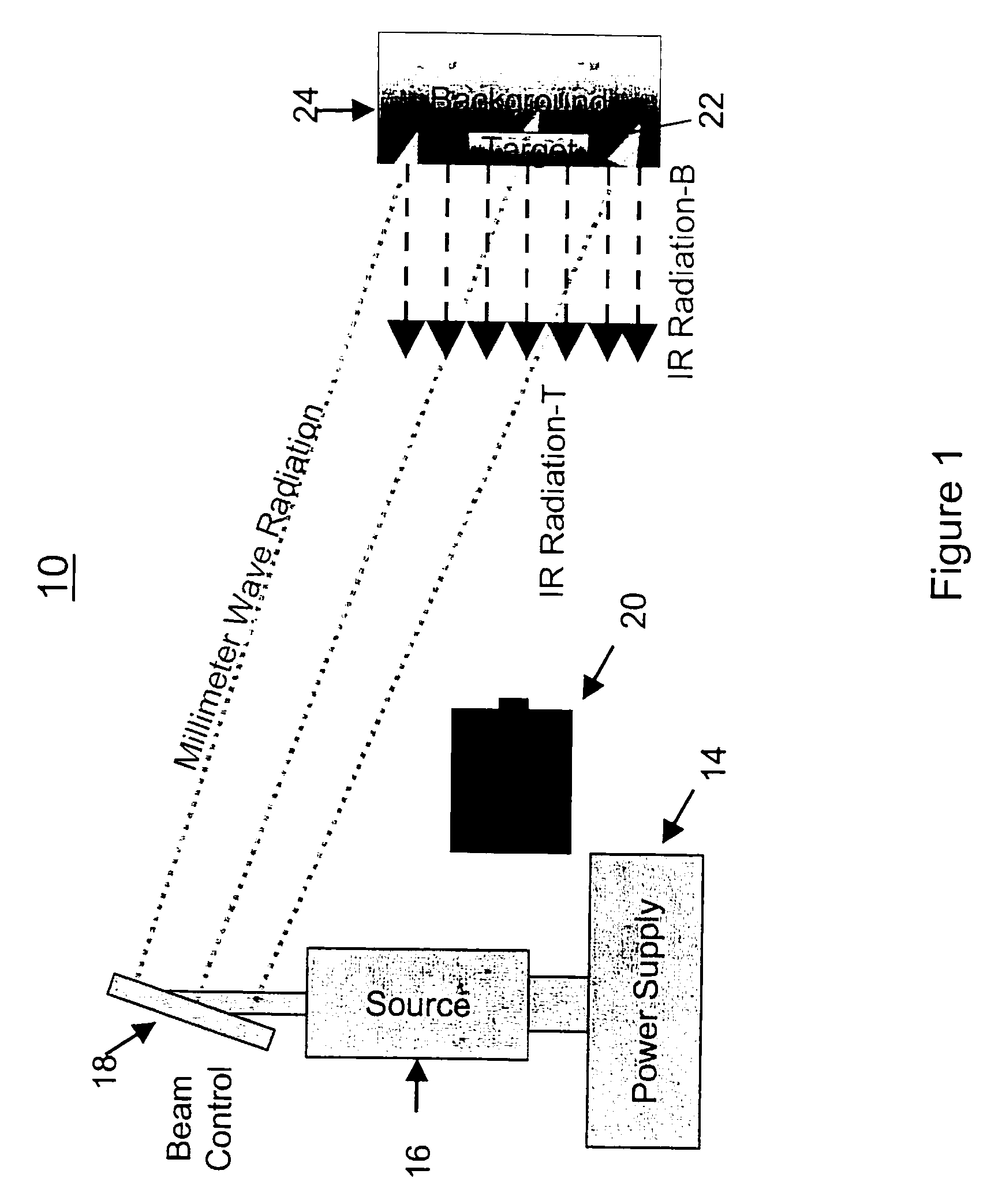
[0035]FIG. 1 shows a system 10 for active thermal imaging according to the invention using a millimeter-wave source (ATIMS). The system 10 includes a high voltage power supply 14, an appropriate microwave source 16, a beam controller system 18, and an infrared (IR) imaging system 20. Microwave source 16 in one embodiment is a continuous wave (CW) gyrotron for generating millimeter-length microwave radiation. The beam controller 18 preferably includes microwave components for smoothing, focusing, and directing the beam. Radiation is directed by the beam controller 18 toward a target 22, which in practice is typically surrounded by a background 24 with different material properties than the target 22. Due to the short wavelength of mm-wave radiation, the spot size of the radiation illuminating the target 22 at ranges of several hundred meters can be relatively small, thus producing sufficient intensity to heat the target and background to slightly different temperatures. This temperat...


PUM


Abstract

A long-range active thermal imaging system includes an electromagnetic radiation source in the range of from about 10 GHz to about 500 GHz; a beam controller for receiving and retransmitting the electromagnetic radiation in a desired direction toward and onto a surface of a target, thereby heating the target and producing an infrared radiation emission from the target surface; and an infrared imager, e.g. an infrared camera coupled to a processor and display, for receiving the target's infrared radiation emission and generating a thermal image of the target. The radiation source may be selected such that the radiation penetrates into the target to provide a thermal signature, e.g. from subsurface features or objects. The thermal signature exhibits rapid changes that can be monitored in real time. This may allow surface or subsurface details or objects to be detected that would not otherwise be apparent.

Description

CROSS-REFERENCE TO RELATED APPLICATIONS[0001]This Application is a Non-Prov of Prov (35 USC 119(e)) application 60 / 726,757 filed on Oct. 7, 2005, incorporated herein by reference.FIELD OF THE INVENTION[0002]The present invention relates to a system and method for active thermal imaging a remote target. More particularly, the invention relates to acquiring an infrared image of a remote target by heating the target with millimeter-length electromagnetic radiation to obtain an enhanced infrared image of the target.BACKGROUND OF THE INVENTION[0003]Thermal imaging is one of a number of techniques for examining or identifying targets or objects. One such technique is passive thermal imaging.[0004]Passive thermal imaging, in which temperature differences in different portions of a target area are detected using infrared cameras or imaging techniques, for example, as described in Gerald C. Hoist, Common Sense Approach to Thermal Imaging, SPIE—the International Society for Optical Engineerin...

Claims


Application Information

Patent Timeline
Patent Type & Authority Patents(United States)
IPC IPC(8): G01J5/00
CPCG01J5/08G01J5/0896G01N25/72G01J2005/0081G01J5/48
Inventor HUBBARD, RICHARD FFLIFLET, ARNE WBOWLES, JEFFREY HKIDWELL, DAVID AHORNSTEIN, MELISSA K.SMITH, GEOFFREY B.LEWIS, III, DAVID
Owner THE UNITED STATES OF AMERICA AS REPRESENTED BY THE SECRETARY OF THE NAVY
Learn More