
Method, apparatus and system for rapid and sensitive standoff detection of surface contaminants

a technology of surface contaminants and standoff detection, applied in the field of applied ultraviolet (uv) raman spectroscopy and chemical detection and identification, can solve the problems of contamination on the surface, none of the above mentioned methods provide adequate detection capabilities, etc., and achieve fast and sensitive standoff, high data throughput, and high spatial resolution

Active Publication Date: 2010-09-14
PERATON INC
View PDF50 Cites 17 Cited by
  • Summary
  • Abstract
  • Description
  • Claims
  • Application Information

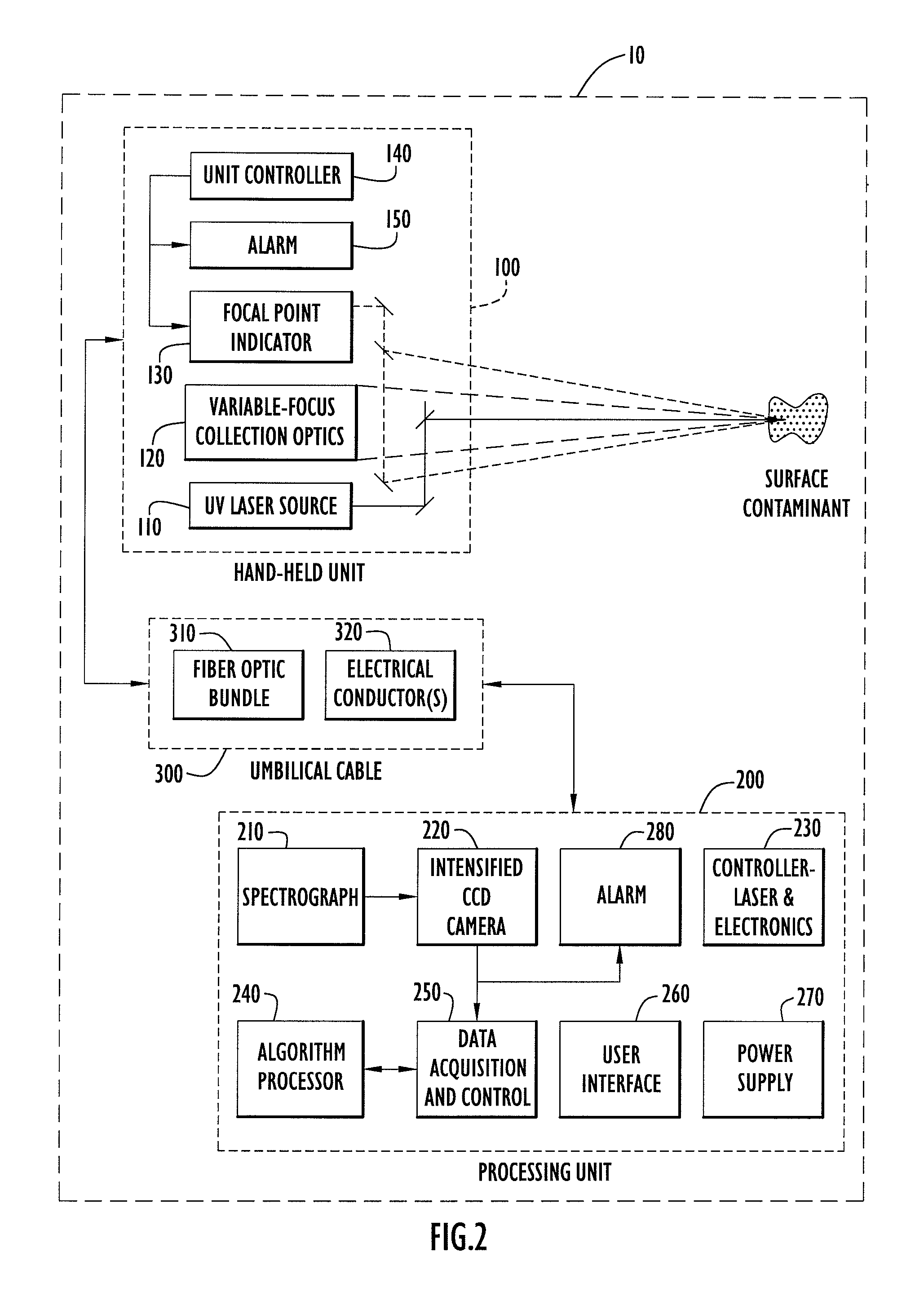
AI Technical Summary

Benefits of technology

[0010]The present invention is directed to systems and methods for fast and sensitive standoff surface-hazard detection with high data throughput, high spatial resolution and high degree of pointing flexibility.
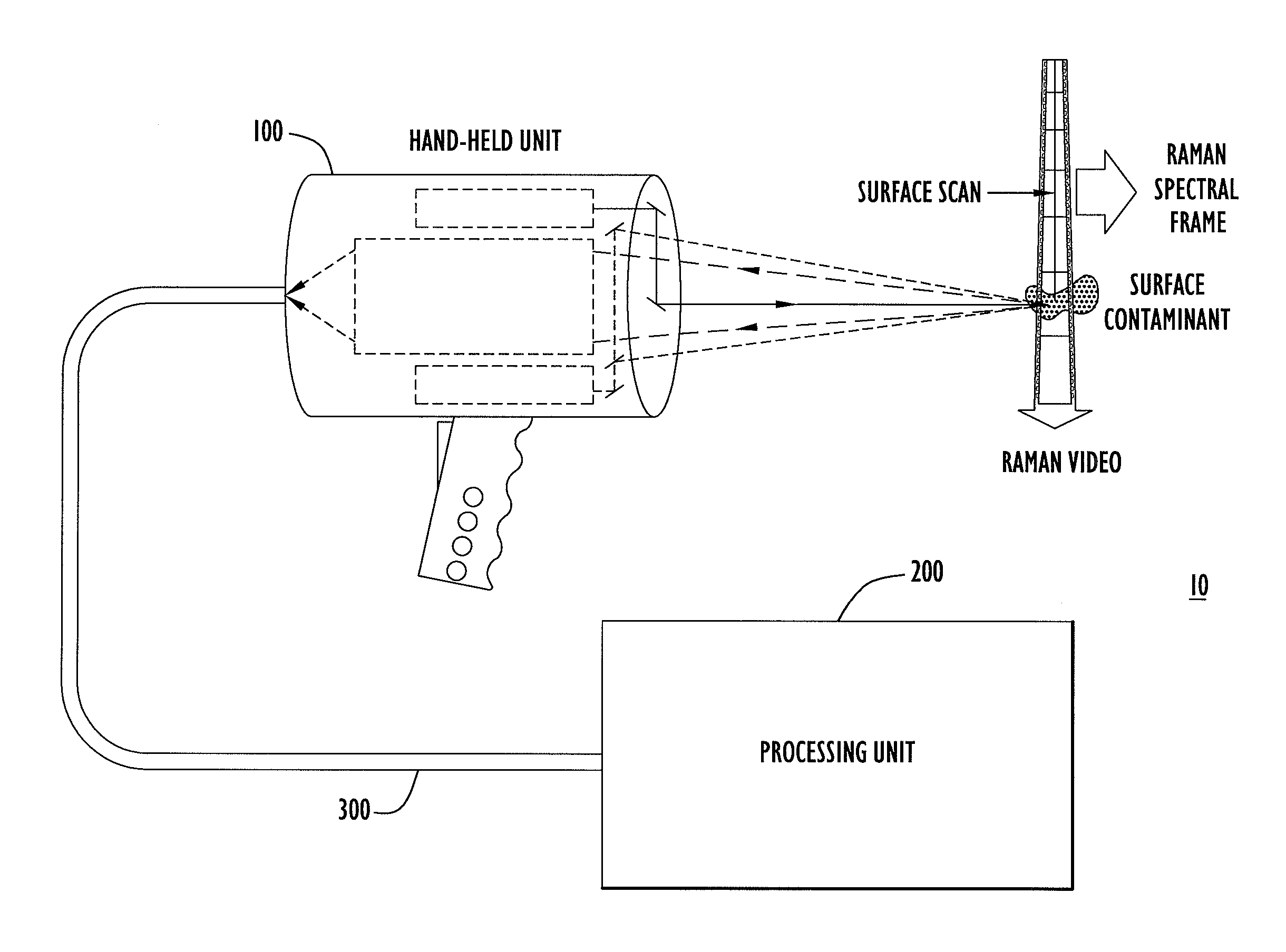
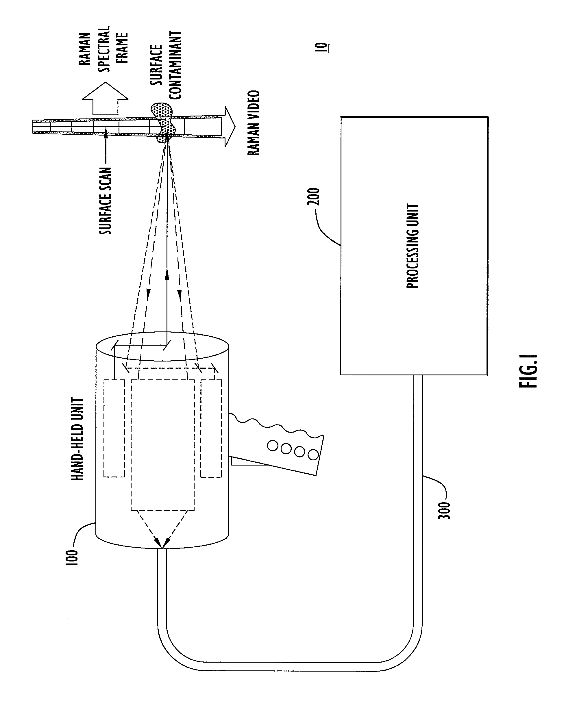
[0011]According to one embodiment of the invention, the system comprises a first hand-held unit that directs an excitation beam onto a surface that is located a distance away from the first unit and an optical subsystem that captures scattered radiation from the surface as a result of the beam of light. The first unit is connected via a link that includes a bundle of optical fibers, to a second unit, called the processing unit. The processing unit comprises a fiber-coupled spectrograph to convert scattered radiation to spectral data, and a processor that analyzes the collected signal and detect the hazardous substance. The second unit may be contained within a body-wearable housing or apparatus so that the first unit and second unit together form a man-portable detection assembly. Adjustable focus collection optics collect the Raman scattered radiation from safer distances, such as more than 0.25 m. To assist in achieving the desired focal distance from the surface to be interrogated, a visible light spot may be projected onto the surface to indicate the optimum standoff range and to indicate the location of the collection field of view.
[0012]The system of the present invention uses a UV-transmitting fiber bundle to efficiently couple the collected scattered radiation image to the spectrograph. A round multi-fiber bundle is positioned at the focal plane of telescope and fibers of the bundle are rearranged to form a single row that is used as the entrance slit of the spectrograph. The spectrograph images the entrance slit onto a pixelated light detector after the light is spatially dispersed by a grating.
[0013]The system and method of the present invention uses the pixelated light detector located at the output of the spectrograph to detect the Raman return. Several Raman returns can be accumulated in order to improve the signal to noise ratio (SNR) of a given measurement frame. A configurable number of returns are accumulated onto the detector to provide a single measurement frame, and each vertical column of pixels of the detector is binned to further improve the SNR. The resulting array of digital values extracted from the detector contains the Raman signature used by the processing unit to make a substance detection and identification. To accommodate various modes of operation of the sensor, the number of Raman returns accumulated in each measurement frame is variable. For example, during rapid search, a surface is quickly scanned and fast frame rates (i.e. less Raman-returns accumulations per frame) are important to maintain high probability of detection. Despite the associated reduction in SNR for each frame, the probability of detection is improved since each frame is composed of short total exposures ensuring a higher probability of grabbing a high-purity Raman signature (low spectral congestion) from a target compound that is being encountered during scan. The short-exposure frames allow the sensor to cope with the quick sequence made of a large variety of surface substances presented to the sensor resulting from the rapid surface-scan. In contrast, during a confirmation or identification mode, the sensor stares at the interrogated surface so that Raman signature have higher purity since less variety is presented to the sensor) and slower frame rates (more Raman-returns accumulations per frame) are important to provide high identification specificity by improving the Raman signature SNR.
[0014]The system and method of the present invention may use a continuous scan of the surface to detect contamination patches. In contrast to the point-and-shoot sensor, this sensor system of the present invention allows for rapid surface scans that range from static to up to tens of centimeters per second depending on the scenario. This is possible since the sensor can output good quality Raman measurement frames at a 10 to 25 Hz rate while maintaining a practical standoff range (i.e., 1 m). The capability to generate these high frame rates allows for capturing of Raman data in the form of “Raman-video” signal. As discussed previously, several modes of operation are possible. A search mode is used to provide maximum scan speed while screening a large perimeter. The high data throughput associated with the search mode is compatible with adaptive sampling techniques that use the real-time results to direct and optimize a search and scanning strategy.
[0015]The detection and identification system of the present invention employ a distributed architecture to maximize system-level performance. For man-portable applications it can be advantageous to separate the system into various units. One unit may be a battery-operated backpack or suitcase unit housing a scaled down version of beam directing, scattering collection and spectrum analysis into an agile configuration. A second unit, called a base station, contains processing capability for more intensive analysis of the collected spectra. Consequently, the battery-operated unit can be made lighter by carrying a small processing device that can execute a less computationally-intensive spectrum analysis algorithm.

Problems solved by technology

Thus, these devices require the operator to approach very close to a potentially harmful substance and maintain proximity to that substance long enough to obtain a single measurement.
The most challenging aspect associated with searching contaminants dispersed on a surface resides in the variety of chemical species a sensor is exposed to during a search.
In the case of persistent patches of contamination composed of thin layers, small droplets or small particles, none of the above mentioned methods provide adequate detection capabilities.

Method used


Image

  • Method, apparatus and system for rapid and sensitive standoff detection of surface contaminants
  • Method, apparatus and system for rapid and sensitive standoff detection of surface contaminants
  • Method, apparatus and system for rapid and sensitive standoff detection of surface contaminants

Examples


Embodiment Construction

[0025]Referring first to FIGS. 1 and 2, a standoff hazard detection system 10 according to an embodiment of the invention is described. The detection system 10 comprises a hand-held unit 100 and a processing unit 200. The hand-held unit 100 is also referred to herein as a first unit or a “wand” unit or device and the processing unit 200 is also referred to herein as a second unit or a data acquisition / processing unit. The hand-held unit 100 is connected by an umbilical cable 300 to the processing unit 200. As used herein, the term “standoff” in connection with a standoff hazard detection and identification system means a distance or range of more than 0.25 meters between the detecting apparatus and the surface that is being interrogated and on which a hazardous substance or contaminant may reside.

[0026]The system 10 achieves fast and sensitive standoff surface-hazard detection with high data throughput, high spatial resolution and high degree of pointing flexibility. This distinctiv...


PUM


Abstract

Systems and methods for fast and sensitive standoff surface-hazard detection with high data throughput, high spatial resolution and high degree of pointing flexibility. The system comprises a first hand-held unit that directs an excitation beam onto a surface that is located a distance away from the first unit and an optical subsystem that captures scattered radiation from the surface as a result of the beam of light. The first unit is connected via a link that includes a bundle of optical fibers, to a second unit, called the processing unit. The processing unit comprises a fiber-coupled spectrograph to convert scattered radiation to spectral data, and a processor that analyzes the collected spectral data to detect and / or identify a hazardous substance. The second unit may be contained within a body-wearable housing or apparatus so that the first unit and second unit together form a man-portable detection assembly. In one embodiment, the system can continuously and without interruptions scan a surface from a 1-meter standoff while generating Raman spectral-frames at rates of 25 Hz.

Description

RELATED APPLICATION[0001]This application claims priority to U.S. Provisional Application No. 60 / 784,465, filed Mar. 22, 2006, the entirety of which is incorporated herein by reference.GOVERNMENT RIGHTS[0002]This invention was made under U.S. Government Contract No. DAAD13-03-D-0018. The U.S. Government may have certain rights in the invention.BACKGROUND OF THE INVENTION[0003]The present invention relates to applied ultraviolet (UV) Raman spectroscopy and chemical detection and identification. More specifically, the present invention relates to devices, systems and methods for remotely detecting hazardous substances that may be on a surface.[0004]In the field of chemical sensing or detecting, it is desirable to quickly detect substances at a contaminated scene and report information about the substances types and locations in order to prevent others from coming into contact or influence with the detected substance. It is also a key factor in improving consequence management by provi...

Claims


Application Information

Patent Timeline
Patent Type & Authority Patents(United States)
IPC IPC(8): G01J3/44
CPCG01J3/02G01J3/0218G01J3/0272G01J3/44G01N21/65G01J3/0291G01N2201/0221
Inventor PONSARDIN, PATRICK LOUISKLETECKA, CHRISTOPHER SCOTTREZAC, JEROMY PAUL
Owner PERATON INC
Learn More