Image correction method and apparatus for use in pattern inspection system

a pattern inspection and image correction technology, applied in the field of image correction and inspection technologies, can solve the problems of unwanted reduction of image quality, increased costs of microfabrication processes of lsi devices, and reduced yield, so as to achieve less image degradation and less setup parameters

Active Publication Date: 2010-09-14
KIOXIA CORP +1
View PDF12 Cites 10 Cited by
  • Summary
  • Abstract
  • Description
  • Claims
  • Application Information

AI Technical Summary

Benefits of technology

[0008]It is an object of the present invention to provide an effective image correction technique which combines together alignment and image correction by use of images as divided by frequency regions and which is less in image degradation and in setup parameters.

Problems solved by technology

In general, microfabrication processes of LSI devices require increased costs, which in turn makes it inevitable for semiconductor manufacturers to improve production yields.
There are several factors which lower yields, one of which factors is the presence of defects in reticle patterns for use during lithography-based exposure and transfer of an ultra-fine circuit pattern onto semiconductor wafers.
Unfortunately, repeated execution of these correcting processes would result in occurrence of accumulated or cumulative errors, which in turn causes unwanted reduction of image quality.
Another problem faced with the prior art is the difficulty in setting of appropriate values of an increased number of model parameters required for each correction and also in setup of an adequate execution order of respective correction processes.

Method used


Image

  • Image correction method and apparatus for use in pattern inspection system
  • Image correction method and apparatus for use in pattern inspection system
  • Image correction method and apparatus for use in pattern inspection system

Examples


Embodiment Construction

[0020]Pattern image correction and image inspection in accordance with illustrative embodiments of this invention will be described with reference to the accompanying drawings below.

(Image Correction Apparatus)

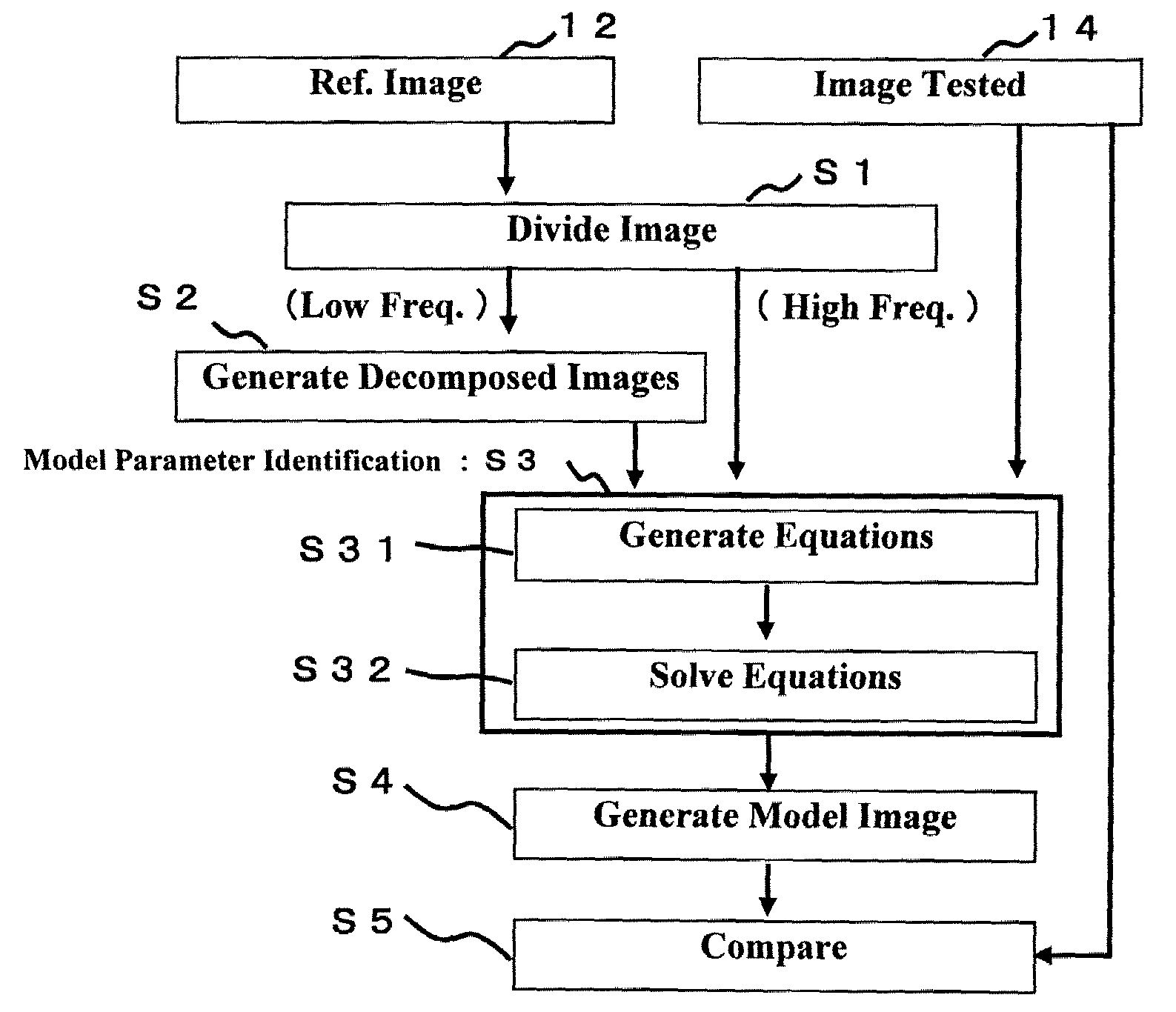
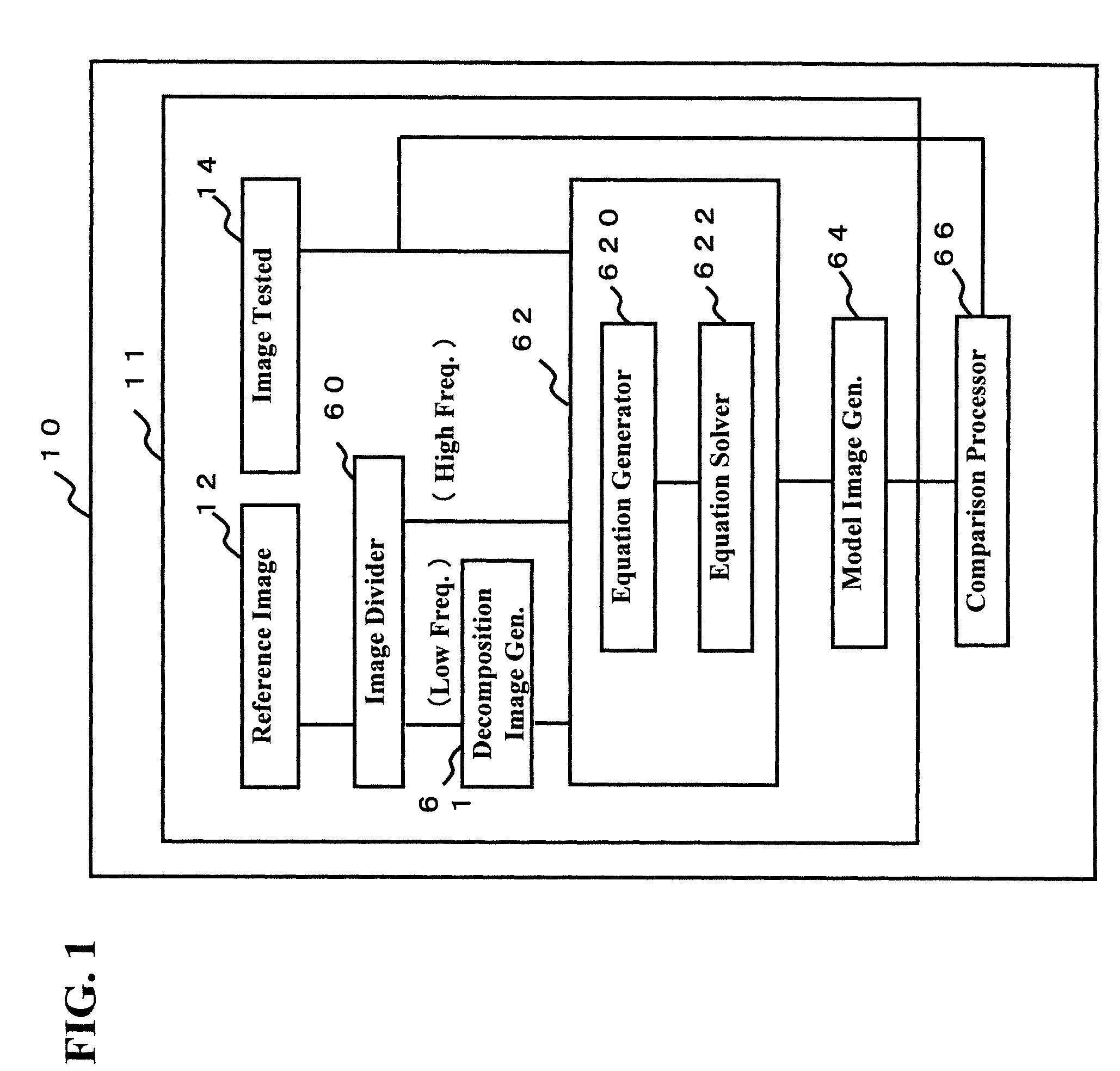
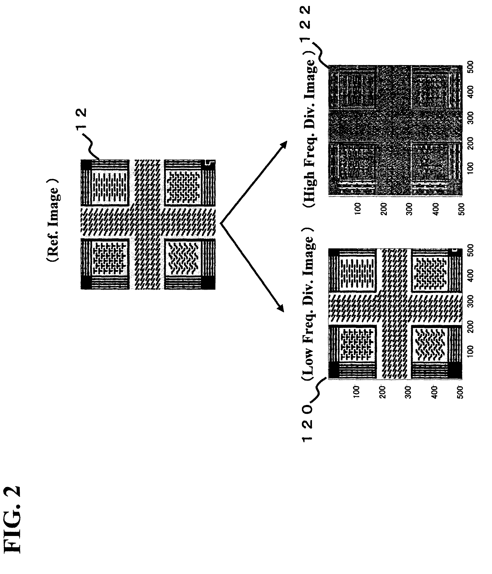
[0021]A configuration of a pattern image inspection apparatus 10 including an image correction device 11 is shown in FIG. 1. The image inspection apparatus 10 is the one that uses the image correction device 11 to generate a model image and compare it to an inspection reference image 14 to thereby detect defects and failures of the image, if any. The image correction device 11 subdivides the reference image 12 into a plurality of image segments of spatial frequency regions, thereby creating more than two frequency division images. The example of FIG. 1 creates a plurality of frequency division images with respect to the reference image 12. The image correction device 11 generates, for one of the frequency division images of the reference image 12, a plurality of decomposed ima...


PUM

PropertyMeasurementUnit
clock frequencyaaaaaaaaaa
frequencyaaaaaaaaaa
frequency divisionaaaaaaaaaa

Abstract

A technique for correcting an image by using frequency division images and decomposition images corresponding in number to reference points is disclosed. An image correction apparatus includes an image divider which divides an inspection reference image into frequency regions to form frequency division images, a decomposition image generator for defining reference points at several locations within at least one frequency division image and for applying weighting with each reference point as a reference to thereby generate decomposition images corresponding in number to the reference points, a model parameter identifier for identifying a model parameter by using 2D linear prediction models of an image being tested, the decomposition images and a frequency division image which is out of the generation of decomposition images, and a model image generator for using the model parameter to generate a model image. An image inspection apparatus using the correction apparatus and an image correction method are also disclosed.

Description

CROSS-REFERENCE TO RELATED APPLICATION(S)[0001]Priority is claimed to Japanese Patent Application No. 2006-227347, filed Aug. 24, 2006, the disclosure of which is incorporated herein by reference.FIELD OF THE INVENTION[0002]The present invention relates generally to image correction and inspection technologies, and more particularly to a method and apparatus for correcting ultrafine pattern images as formed on reticles for use in the manufacture of highly integrated semiconductor circuit devices, such as LSI chips. This invention also relates to a pattern inspection apparatus which uses the image correction technique to inspect a pattern image for defects.RELATED ART[0003]In general, microfabrication processes of LSI devices require increased costs, which in turn makes it inevitable for semiconductor manufacturers to improve production yields. There are several factors which lower yields, one of which factors is the presence of defects in reticle patterns for use during lithography-...

Claims


Application Information

Patent Timeline
Patent Type & Authority Patents(United States)
IPC IPC(8): G06K9/00G06K9/62G01N21/956G03F1/84G06T1/00
CPCG06T7/001G06T5/50G06T2207/30148G06T2207/20021
Inventor OAKI, JUNJI
Owner KIOXIA CORP
Why Eureka
Try Eureka