
Charging handle with forward assist function

a charging handle and forward assist technology, applied in the field of firearms, to achieve the effect of improving the charging handle of the firearm, increasing utility, and ensuring the safety of the firing bolt group

Active Publication Date: 2010-09-21
MAGPUL INDUSTRIES
View PDF14 Cites 142 Cited by
  • Summary
  • Abstract
  • Description
  • Claims
  • Application Information

AI Technical Summary

Benefits of technology

The improved charging handle enhances user control and simplifies operation and maintenance by allowing full-length assist functionality without special user motions, ensuring efficient bolt carrier management and reduced maintenance needs.

Problems solved by technology

This can occur due to debris, fouling, a weakened action spring or magazines which require additional feeding force.

Method used


Image

  • Charging handle with forward assist function
  • Charging handle with forward assist function
  • Charging handle with forward assist function

Examples


Embodiment Construction

[0031]With reference now to the drawings, the preferred embodiment of the firearm is herein described. It should be noted that the articles “a”, “an” and “the”, as used in this specification, include plural referents unless the content clearly dictates otherwise.

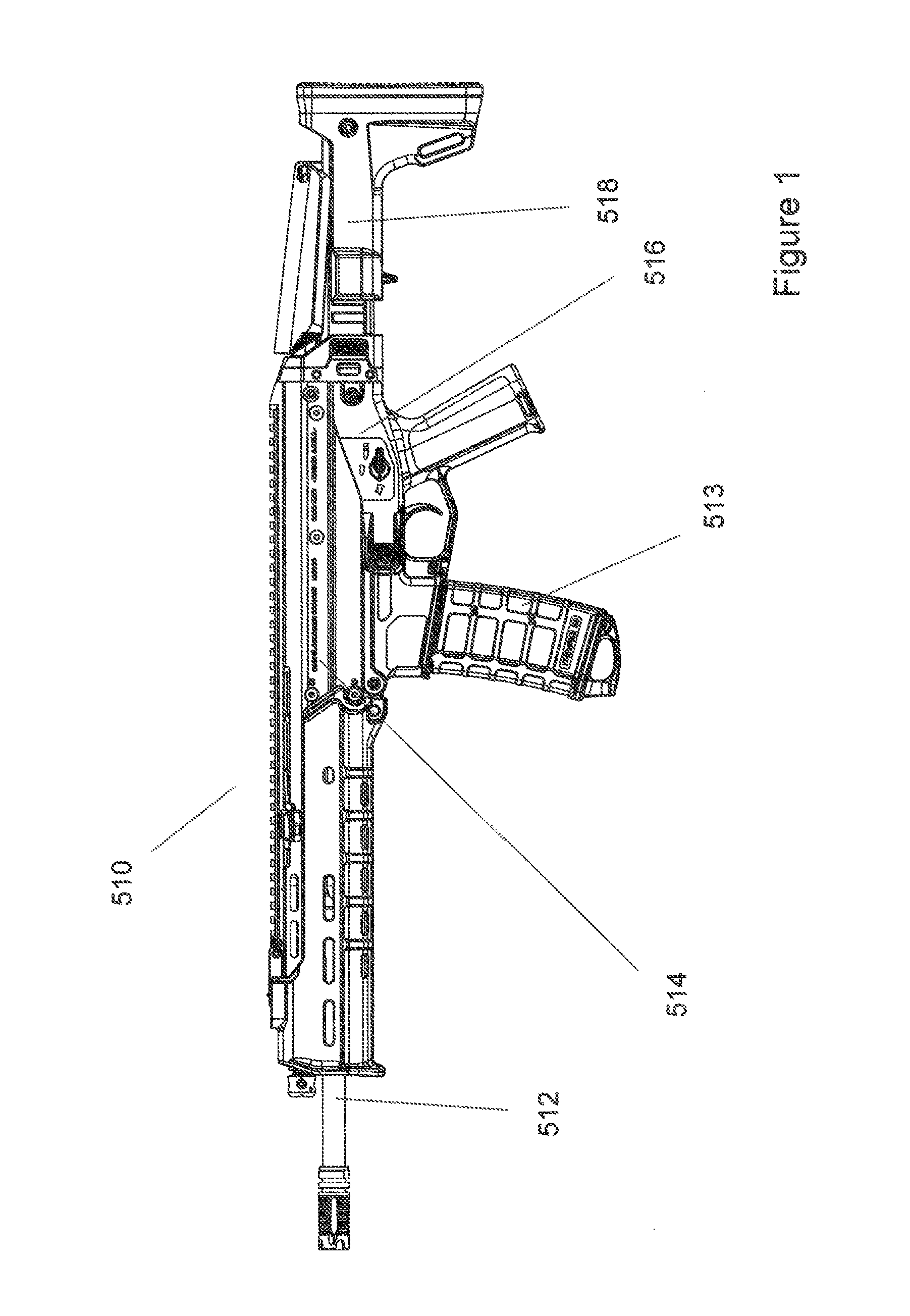
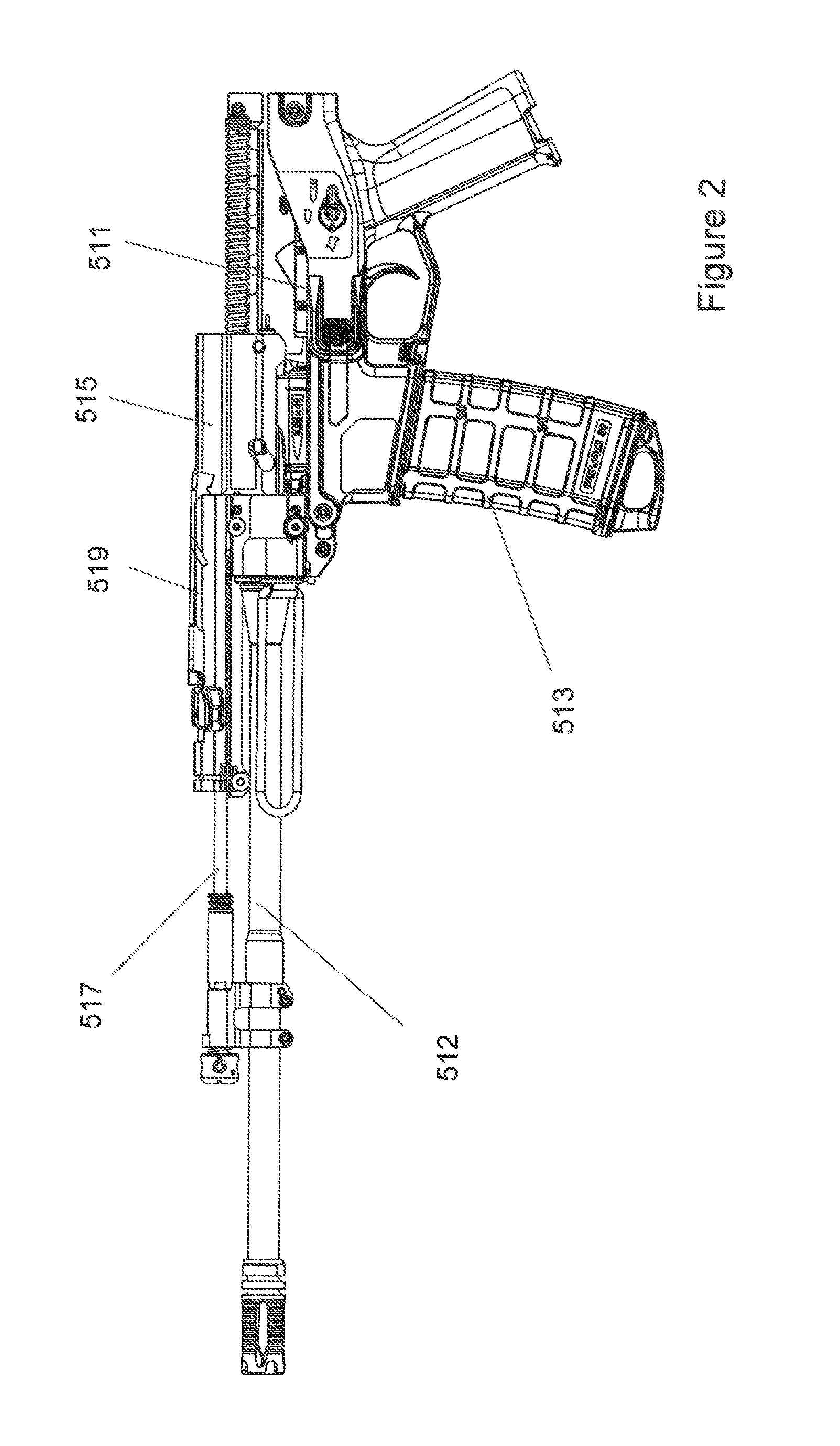
[0032]With reference to FIGS. 1 and 2, the firearm 510 has four major components, namely the barrel 512, upper receiver 514, grip housing 516 and stock 518. Internal parts are generally located in the receiver 514 and grip housing 516. A trigger control group 511 and a magazine 513 reside in the grip housing 516 and a short stroke gas piston system 517 and charging system 519 and bolt carrier 515 reside in the receiver 514. The firing pin is also located in the receiver 514. As shown in FIG. 4, barrel 512 rests in barrel trunnion 522 in a cantilevered fashion. Gas piston system 517 resides over the barrel 512. Bolt carrier 515 rests against the barrel trunnion 522 when it is in a rest position. The charging handle 519 reside...


PUM


Abstract

The present invention is an improved charging handle for a firearm. The handle is generally non-reciprocating and features a user activated forward assist. The major components are an actuator to provide charging function and upon which other components are mounted, a spring biased lever with a hook which biases downward so that the hook may interface a bolt carrier when the lever is activated, and a blade upon which handle structure is mounted. In the preferred embodiment, the handle is ambidextrous and features a spring detent to keep it in stowed position until the user desires use. The handle will only reciprocate when the lever is activated, which in turn requires intentional user action, thereby providing a relatively safer weapon to operate.

Description

CROSS-REFERENCES TO RELATED APPLICATIONS[0001]This Application claims priority as a non-provisional perfection of prior filed U.S. Provisional Application 60 / 884,615, filed on Jan. 11, 2007 and incorporates the same by reference in its entirety.FIELD OF THE INVENTION[0002]The present invention relates to the field of firearms and more particularly relates to a new charging handle for a firearm with a forward assist function.BACKGROUND OF THE INVENTION[0003]Prior firearms have been, as a whole, adequate for their purposes. However, the advent of improved technologies in other fields, combined with the demands of current military tactics, both offensive and defensive, have created a need for a firearm that improves upon the current designs in the art. Practically speaking, the need has arisen for a lighter and more efficient weapon; one that is easily maintained, simple to operate and assemble, and easily enhanced as need requires. This includes the various parts of the firearm, such ...

Claims


Application Information

Patent Timeline
Patent Type & Authority Patents(United States)
IPC IPC(8): F41A3/72
CPCF41A21/481
Inventor FITZPATRICK, RICHARD M.MAYBERRY, MICHAELNAKAYAMA, BRIANBURT, ERIC
Owner MAGPUL INDUSTRIES
Learn More