Suction unit

a technology of suction unit and cylinder, which is applied in the direction of machine supports, door/window protective devices, manufacturing tools, etc., can solve the problems of wafer w damage, and achieve the effects of reducing the number of components, reducing the pressure within the internal space of the groove, and simplifying the apparatus

Active Publication Date: 2010-09-21
LINTEC CORP
View PDF6 Cites 17 Cited by
  • Summary
  • Abstract
  • Description
  • Claims
  • Application Information

AI Technical Summary

Benefits of technology

[0021]According to the present invention, when the suction is performed through the suction face to suck the adhesive sheet, the suction flow is generated from a gap between the adhesive sheet and the groove at the outer side of the suction face towards the suction face. Owing to this suction, the pressure within the internal space of the groove is reduced, and the adhesive sheet overlapping a groove sinks downwards into the groove. Accordingly, for example, the protection tape is stuck on the other surface of the plate-like member, and thereafter when the peeling tape for peeling the protection tape is stuck to the outer side edge of the protection tape by an elastically deformable roller, the adhesive sheet is kept away from the peeling tape due to sinking lower of the adhesive sheet; thus the protection tape and the adhesive sheet are prevented from unintentional adhering to each other. Owing to this arrangement, conventional structure for moving the mask plate and plate-like member is not required. Accordingly, the number of components can be reduced and simplification of the apparatus can be achieved. Furthermore, the moving operation of the mask plate to prevent the peeling tape from adhering to the adhesive tape can be eliminated. Thus, the necessary processing time for peeling off can be reduced.
[0022]In addition, the suction face has a plane shape corresponding to the plane shape of the plate-like member, and the groove is positioned along the periphery of the suction face. Accordingly, close positioning of the suction face and the groove to each other can help the pressure reduction of the groove by the suction effectively; thus, the adhesive sheet and the peeling tape can be prevented from adhering to each other more reliably.
[0023]Further, a plurality of grooves are formed along the direction from the center of the suction face to the periphery thereof. Even when holding plate-like members of various plane sizes, a groove can be located at a position along the periphery of the plate-like member corresponding to the size. Thus, the applicability of the suction unit is enhanced.
[0024]Furthermore, the extending length of the groove is arranged to be larger than the shorter width of the peeling tape. Accordingly, the adhesive sheet can be sunk across the full shorter width of the peeling tape. Thus, the adhesive sheet and the peeling tape can be prevented from adhering to each other more reliably and the peeling off of the protection tape can be carried out smoothly.

Problems solved by technology

When peeling off the protection tape H is started in that state, the wafer W is damaged.

Method used


Image

  • Suction unit
  • Suction unit
  • Suction unit

Examples


first embodiment

[0050]FIG. 1 is a schematic view showing an arrangement of a peeling unit to which a suction unit in accordance with a first embodiment is applied. In FIG. 1, a peeling unit 10 includes a suction unit 12, which is supported movably by a slider 11 extending in the right / left direction in FIG. 1, and a peeling means 13 disposed above the suction unit 12.

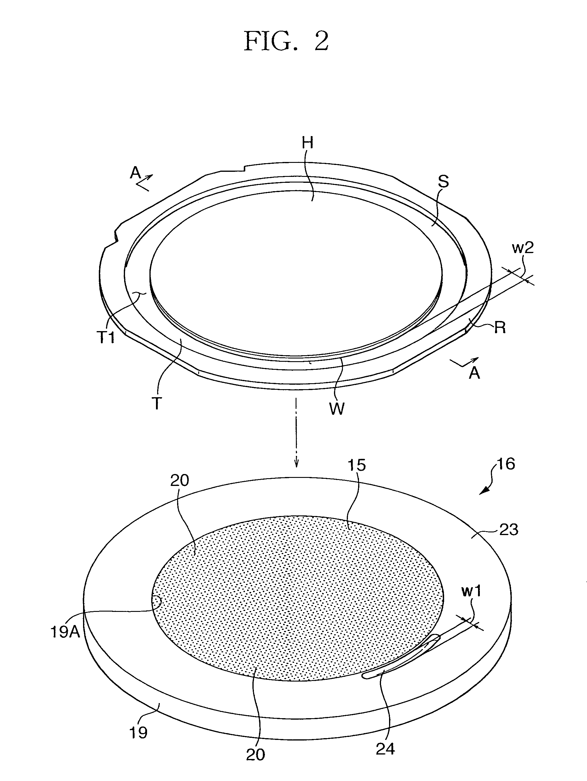
[0051]As shown in FIG. 2 and FIG. 3, a wafer W as a plate-like member, which is held by the suction unit 12, is formed in an almost disk-like shape, and is supported by a ring frame R via a dicing tape T as an adhesive sheet. Specifically, the dicing tape T has an adhesive face T1 on its upper face, and is stuck to the rear surface (bottom surface) of the wafer W via this face T1. The dicing tape T is formed in a plane area that is larger than the wafer W, and has a plane area protruding outside of the periphery of the wafer W, the periphery side of which is stuck to the bottom surface of the ring frame R. A substantially ring-shape sp...

second embodiment

[0064]Next, a second embodiment of the present invention will be described. In the following description, as for the identical or equivalent portions to those in the first embodiment, the same reference codes will be used, if necessary, and the description thereof will be omitted or made just simply.

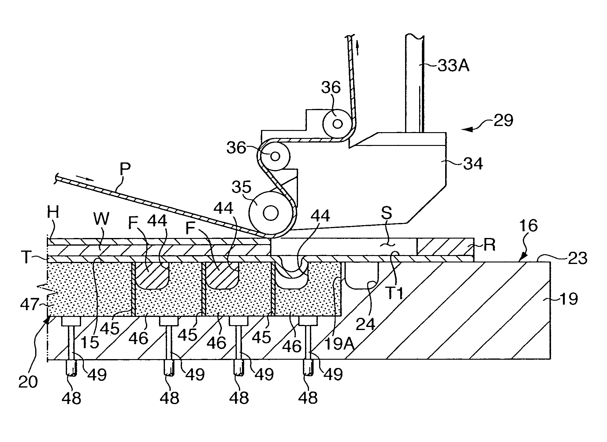
[0065]FIG. 10 and FIG. 11 show a suction unit according to a second embodiment of the present invention. The second embodiment is characterized in that a plurality of grooves 44 are formed within the suction face 15 in the first embodiment.

[0066]In the suction member 20 according to the second embodiment, three partitioning walls 45 positioned substantially concentrically with respect to the periphery of the suction face 15 are formed. These partitioning walls 45 partition the suction member 20 into three ring members 46, which have a doughnut-like shape respectively viewed from the top, and a disk member 47, which is positioned inside the partitioning wall 45 at the most inner side. The...


PUM

PropertyMeasurementUnit
areaaaaaaaaaaa
radiusaaaaaaaaaa
suctionaaaaaaaaaa

Abstract

A wafer W is supported on the rear surface side thereof by a ring frame R by means of a dicing tape T, and a protection tape H is stuck on the front surface side the wafer W. A suction unit 12 includes a table 16 having a suction face 15 in the upper face. The suction face 15 sucks the dicing tape T to hold the wafer W through performing a predetermined suction. At least in a partial area along the periphery of the suction face 15, a groove 24 is formed. By sucking through the suction face 15, the inside of the groove 24 becomes negative pressure and the dicing tape T is sunk therein.

Description

TECHNICAL FIELD[0001]The present invention relates to a suction unit for holding a plate-like member stuck with an adhesive sheet on one surface, further in particular, to a suction unit capable of peeling off easily and swiftly the protection tape stuck on the other surface of the plate-like member.BACKGROUND ART[0002]Conventionaly, a substantially disk-like semiconductor wafer (hereinafter, simply referred to as “wafer”) of which front surface side is the circuit plane is known. Generally, the thickness of the wafer is controlled by grinding the rear surface side with a grinder or the like after sticking a protection tape on the circuit plane. Then, in a state that the rear surface side of the wafer is stuck to the adhesive face side of a dicing tape exposed within the inner side of the ring frame, the protection tape is peeled off from the front surface side of the wafer. And after that, the wafer is cut into a dice shape; thus, the semiconductor chip is formed.[0003]As an appara...

Claims


Application Information

Patent Timeline
Patent Type & Authority Patents(United States)
IPC IPC(8): B32B38/10B32B11/00H01L21/677H01L21/00H01L21/304H01L21/68H01L21/683
CPCH01L21/67132H01L21/6835H01L21/6836H01L2221/68327H01L2221/6834Y10T156/19H01L2924/3025Y10T156/1978Y10T156/1944Y10T156/1132Y10T156/1168H01L2221/68395H01L21/02H01L21/304
Inventor KOBAYASHI, KENJITSUJIMOTO, MASAKIYOSHIOKA, TAKAHISA
Owner LINTEC CORP
Why Eureka
Try Eureka