
Surgical insertion tool

Inactive Publication Date: 2010-09-21
BOSTON SCI NEUROMODULATION CORP
View PDF132 Cites 54 Cited by
  • Summary
  • Abstract
  • Description
  • Claims
  • Application Information

AI Technical Summary

Benefits of technology

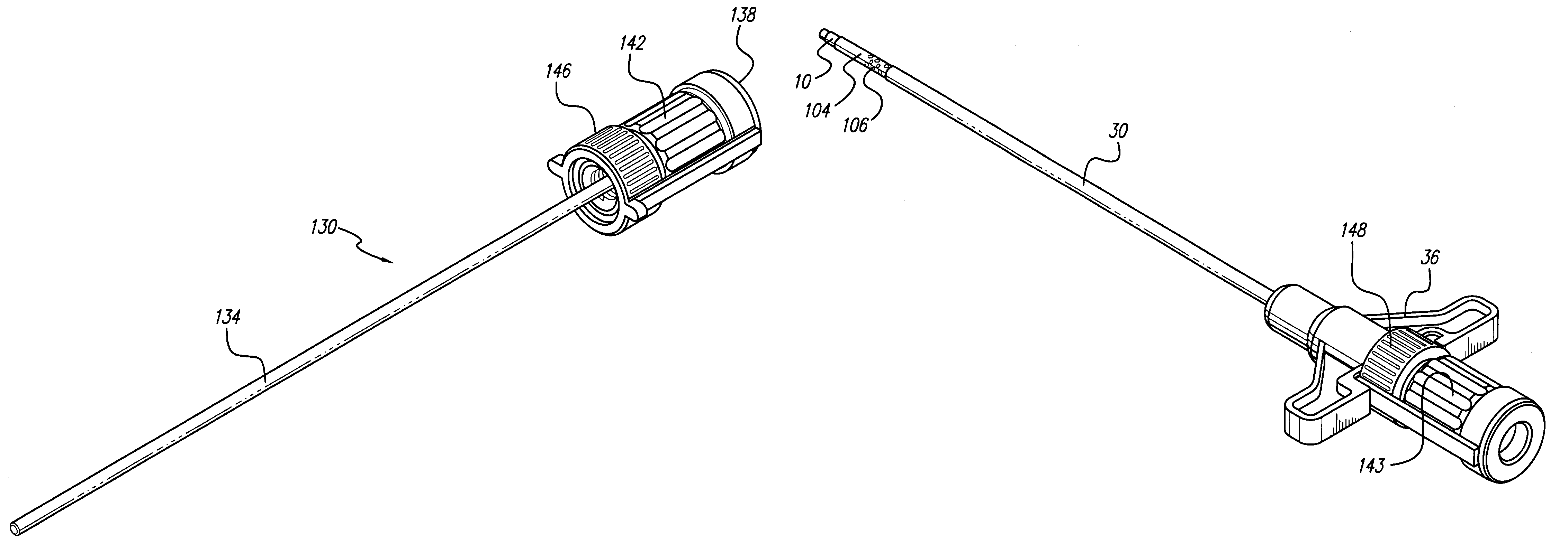
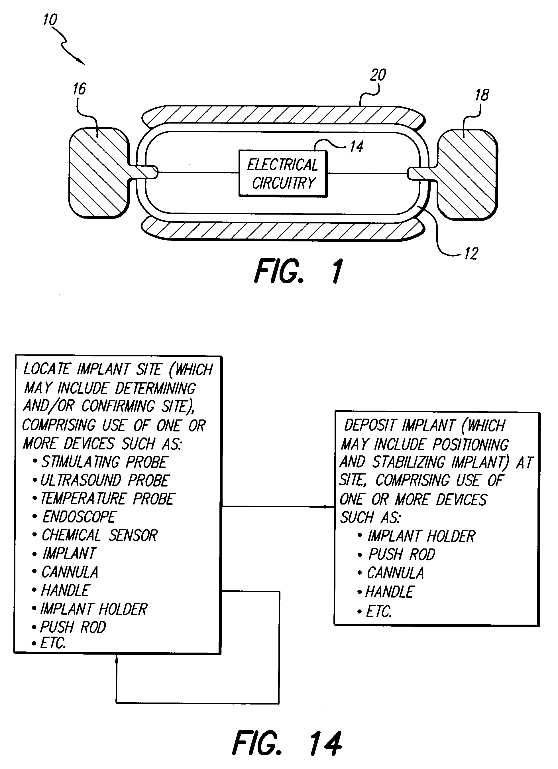
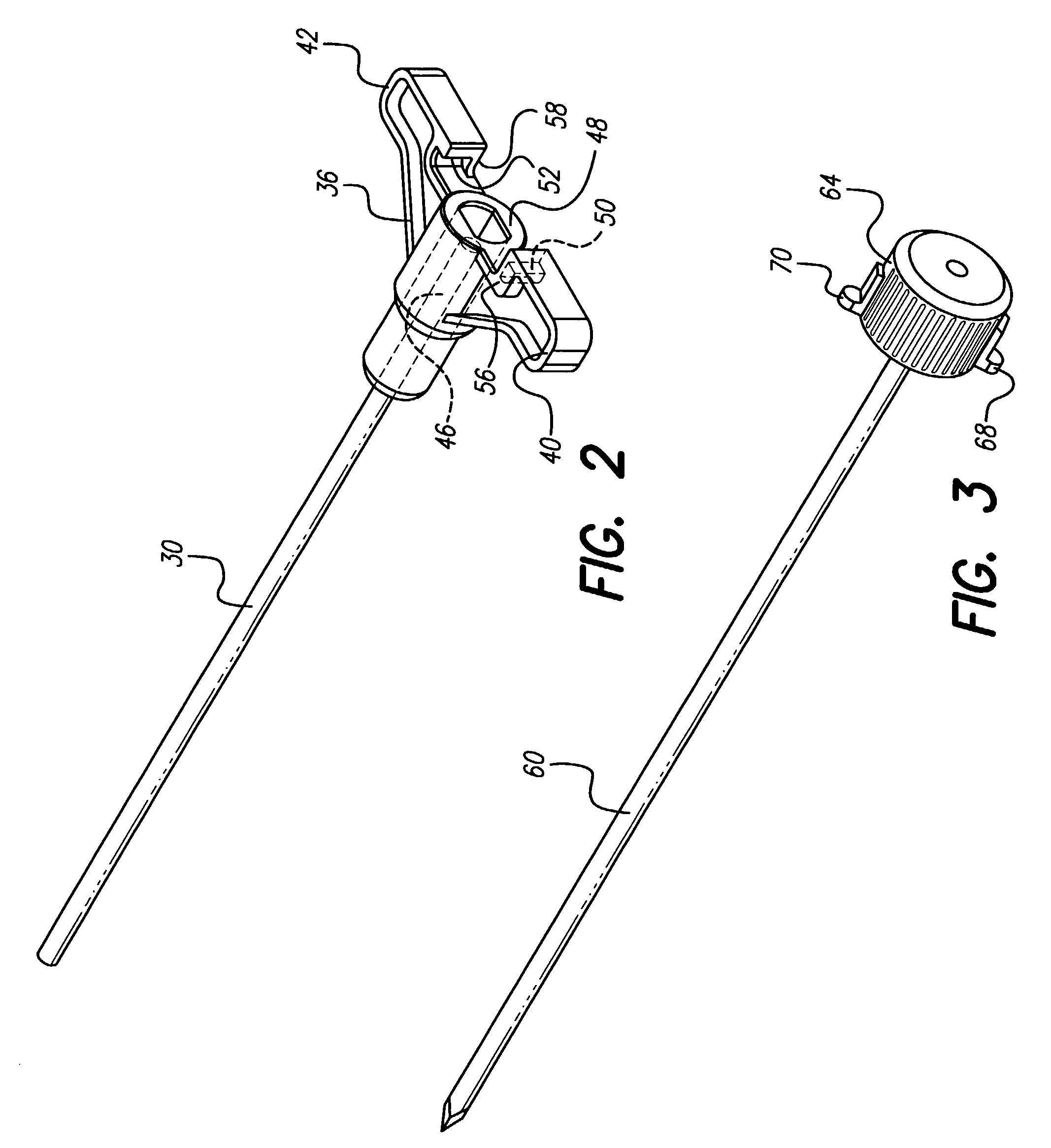
[0011]In a primary embodiment, a trocar, scalpel, or other standard instrument is used to facilitate entry through the skin. A stimulating probe is inserted into the cannula of the tool and is used to bluntly dissect to the implant area. With the probe tip at a probable implant site, electrical impulses are delivered to the probe tip to test the area and determine and / or confirm the desired implant site. Once an acceptable site is found, the stimulating probe is removed from the cannula, and an implant holder containing a BION stimulator is inserted into the cannula. The implant is packaged and provided in the implant holder, which ensures proper electrical polarity, and helps protect and ease handling of the BION device.

Problems solved by technology

Unfortunately, the implant site determined by the first set of tools may not easily be located with the implant insertion tools.
In addition, the implantation of microminiature stimulators (also referred to as BION® microstimulators) heretofore would have required the use of multiple surgical instruments and / or instruments not ideally suited for the insertion of such a device.

Method used


Image

  • Surgical insertion tool
  • Surgical insertion tool
  • Surgical insertion tool

Examples


Embodiment Construction

[0036]The following description is of the best mode presently contemplated for carrying out the invention. This description is not to be taken in a limiting sense, but is made merely for the purpose of describing the general principles of the invention. The scope of the invention should be determined with reference to the claims.

[0037]For illustration purposes, the following description of the present invention is shown in conjunction with a microminiature, implantable, leadless stimulator 10, such as a BION® microstimulator, illustrated, e.g., in FIG. 1. The device 10 includes a narrow, elongated capsule 12 containing electronic circuitry 14 connected to electrodes 16 and 18, which pass through the walls of the capsule at either end, together forming a microstimulator of the type disclosed and fully described in U.S. Pat. Nos. 5,193,539 and 5,193,540, both of which are incorporated herein, in their entirety, by reference. As detailed in the referenced patents, and mentioned later h...


PUM


Abstract

A tool is provided for facilitating determining a proper location for an implantable device or medication, and for then delivering the implant to the precise location determined with the tool. To determine the target location, the tool may include a component for testing target locations, such as a stimulating probe for simulating a miniature implantable stimulator. In one embodiment, the tool is used to test a miniature implantable stimulator prior to depositing the implant precisely at the target location. The components of the tool are configured to maintain the implant at the target location while the tool is withdrawn. In one embodiment, a push rod assembly of the tool keeps the implant in position while it retracts the implant holder from around the implant. The ergonomic and light-weight tool leads to reduced surgical time, number and size of incisions, risk of infection, and likelihood of error.

Description

[0001]This application is a Continuation of U.S. patent application Ser. No. 09 / 761,934, filed Jan. 17, 2001, now allowed as U.S. Pat. No. 6,582,441, issued on Jun. 24, 2003, which patent in turn claims the benefit of U.S. Provisional Patent Application Ser. No. 60 / 184,561, filed Feb. 24, 2000, which patent and application are both incorporated herein by reference in their entirety.FIELD OF THE INVENTION[0002]The present invention generally relates to implantation of a medical device or medication in a living body, and more particularly relates to an insertion tool for implanting a medical device or medication in a living body.BACKGROUND OF THE INVENTION[0003]A variety of mechanisms exist for the implantation or injection of devices or medications within a living body. Items such as medicinal pellets or rods, contraceptive capsules, and sensors or identification transponders may be implanted at a target location within a human or other body. The associated procedures often employ mu...

Claims


Application Information

Patent Timeline
IPC IPC(8): A61B19/00A61N1/05
CPCA61N1/05A61N1/0551
Inventor HE, TOM XMCGIVERN, JAMES PWHITEHURST, TODD K
Owner BOSTON SCI NEUROMODULATION CORP
Learn More