LED drive circuit

a technology of led drive and circuit, which is applied in the direction of static indicating devices, instruments, semiconductor lamp usage, etc., can solve the problems of increasing power prs consumption, thermal runaway, shorting across the malfunctioning led(s), etc., and achieves less power consumption, reduce current flowing, and reduce voltage

Inactive Publication Date: 2010-09-21
STANLEY ELECTRIC CO LTD
View PDF11 Cites 20 Cited by
  • Summary
  • Abstract
  • Description
  • Claims
  • Application Information

AI Technical Summary

Benefits of technology

[0025]The ambient temperature surrounding the LED unit may rise, resulting in a lowering of the forward voltage of the LEDs contained in the LED unit. Even in this case, the LED drive circuit of the disclosed subject matter comes to a state of negative feedback in terms of power that works to lower the voltage for driving the LED unit and reduce the current flowing in the LED unit. Thus, the LED drive circuit is operative to suppress the self-exothermicity of the LED and block the thermal runaway of current.
[0026]The LED unit has circuitry with less power consumption and a higher efficiency of power utilization because it requires less current flowing in the positive temperature coefficient resistor.
[0027]The LED drive voltage to be controlled is not dependent on the current flowing in the LED unit. Therefore, even if a malfunction occurs in at least one of the LEDs contained in the LED unit LU and makes it short across the malfunctioning LED(s), the LED drive voltage is prevented from abnormally elevating (that is, prevented from causing an overvoltage), and any protective circuit is not required.

Problems solved by technology

This is a state of positive feedback in terms of power, which can eventually lead to thermal runaway, which is a concern.
From the viewpoint of circuit characteristic, the circuit for constant-current driving the LED unit LU can cause an abnormal elevation in the output voltage Vo (i.e., can cause an overvoltage) at no load (for example, when a malfunction occurs in at least one of the LEDs contained in the LED unit LU resulting in a short across the malfunctioning LED(s) in the circuit).
Therefore, an increase in the current value Il of the LED drive current IL flowing in the LED unit LU in order to develop a higher brightness at the LED unit LU also increases the power PRS consumed at the current sense resistor RS, and increases the power loss correspondingly.

Method used


Image

  • LED drive circuit
  • LED drive circuit
  • LED drive circuit

Examples


Embodiment Construction

[0032]The disclosed subject matter will now be described below in detail with reference to FIGS. 1-3. The below-described embodiment is a specific example of the disclosed subject matter and accordingly is given various technical features, though the scope of the disclosed subject matter is not limited to the embodiments.

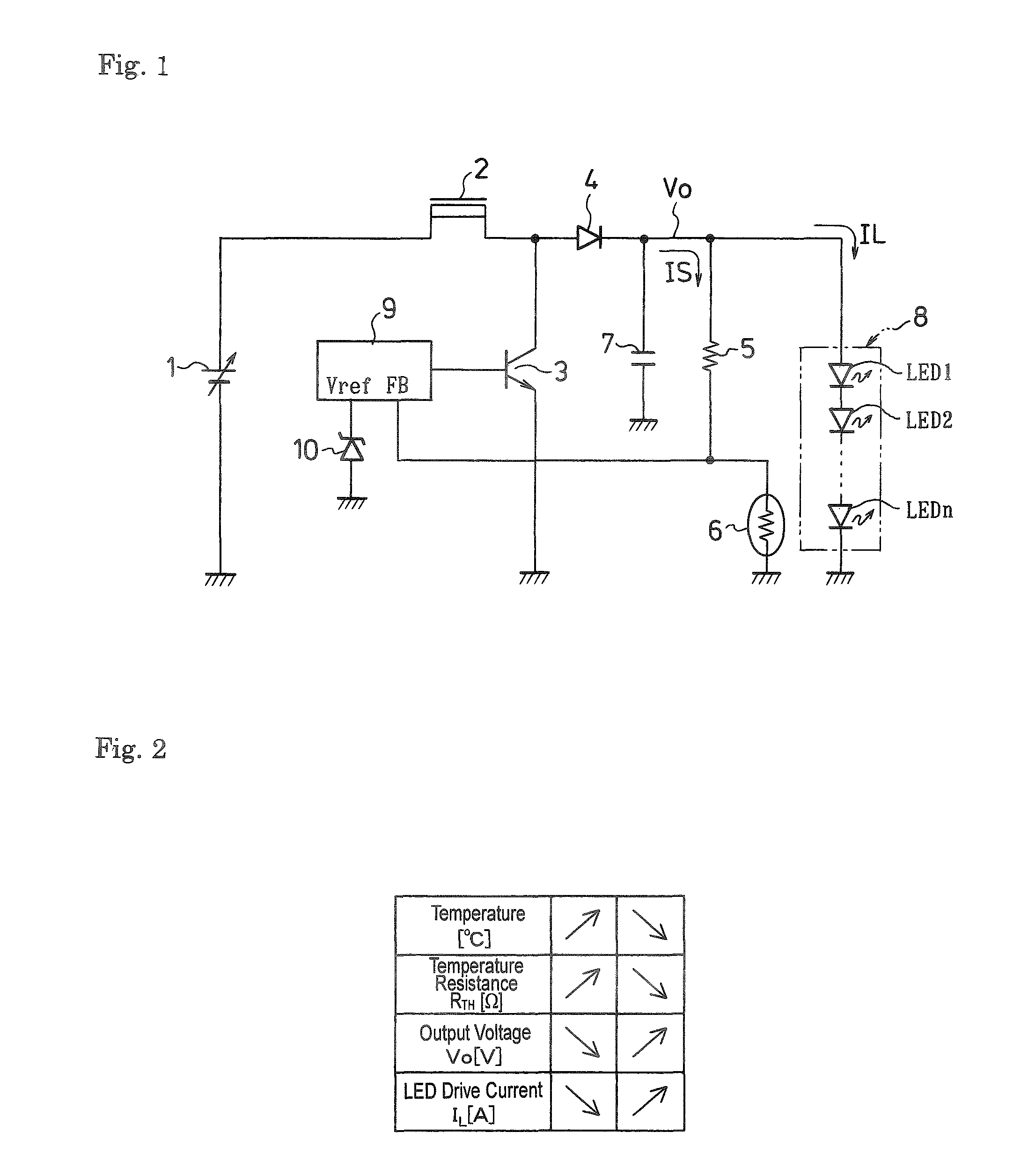
[0033]FIG. 1 is a circuit diagram illustrative of an embodiment associated with an LED drive circuit made in accordance with principles of the disclosed subject matter. This circuitry includes a choke coil 2 having one end connected to a DC power source 1 and the other end connected to a collector of an NPN transistor 3 having a grounded emitter and to an anode of diode 4.

[0034]A resistor 5 can be provided having one end connected to a cathode of the diode 4 and the other end connected to one end of a positive temperature coefficient resistor 6 whose other end is grounded. The cathode of the diode 4 can be connected to one end of a capacitor 7 (also known as a conde...


PUM


Abstract

An LED drive circuit of the disclosed subject matter can include an LED unit and a serial circuit connected in parallel therewith. The serial circuit includes a resistor and a positive temperature coefficient resistor having a positive linear temperature coefficient. A voltage across the positive temperature coefficient resistor is fed back to an output control circuit. An output voltage that is PWM-controlled on the basis of a reference voltage set at the output control circuit is used to drive the LED unit.

Description

[0001]This application claims the priority benefit under 35 U.S.C.§119 of Japanese Patent Application No. 2006-076896 filed on Mar. 20, 2006, which is hereby incorporated in its entirety by reference.BACKGROUND[0002]1. Field[0003]The disclosed subject matter relates to an LED drive circuit, and particularly to an LED drive circuit capable for a light emitting diode (LED) that maintains a constant brightness even if temperature environments such as ambient temperature and self-exothermicity vary.[0004]2. Description of the Related Art[0005]Performance of a PN-junction bandgap in an LED has temperature dependence and can decrease as the temperature rises. Therefore, the forward voltage of the LED has negative temperature dependence and lowers characteristically as the temperature rises.[0006]When the LED is constant-voltage driven, therefore, an elevation in the temperature at the LED due to the ambient temperature and self-exothermicity can lower the forward voltage and increase the ...

Claims


Application Information

Patent Timeline
Patent Type & Authority Patents(United States)
IPC IPC(8): G09G3/32G09G3/14H01L33/00H05B44/00
CPCG09G3/14H05B33/089G09G3/2014G09G2320/0233G09G2320/041G09G2330/028Y02B20/341Y02B20/30H05B45/56
Inventor FUJINO, TAKASHI
Owner STANLEY ELECTRIC CO LTD
Why Eureka
Try Eureka