OCT probe for eliminating ghost images

a technology of oct probe and ghost image, which is applied in the field of oct probe for eliminating ghost images, can solve the problems of difficult to image the biological functions of subjects, low spatial resolution of ultrasound endoscopic probes, and use of x-rays, and achieves the effect of preventing the generation of ghost images due to multiple reflections, and reducing the size of the spo

Inactive Publication Date: 2010-09-28
NAMIKI PRECISION JEWEL CO LTD
View PDF6 Cites 119 Cited by
  • Summary
  • Abstract
  • Description
  • Claims
  • Application Information

AI Technical Summary

Benefits of technology

[0013]It is a further object of the present invention to extend the work distances and to decrease the diameters of spot sizes in OCT probes having the above configurations.
[0051]In the OCT probe of the present invention, the anti reflection coating, which is non reflective with respect to light that enters the light output surface, may be formed on the light output surface of the optical system. In this case, reflection of the propagating light at the light output surface is prevented, and accordingly multiple reflection is further suppressed, and the generation of ghost images can be positively prevented.

Problems solved by technology

However, utilization of X rays has problems, such as the fact that subjects are irradiated with radiation, and that it is difficult to image the biological functions of the subjects.
However, the spatial resolution of ultrasound endoscopic probes is not high, and it is not possible to obtain information of biological tissue except the shape thereof.
Further, media such as water are necessary to utilize ultrasound endoscopic probes, and therefore, the processes involved in observation of subjects are complex.
However, there is a problem that it is difficult for the OCT endoscopic probe disclosed in PCT Japanese Publication No. 2005-533610 to achieve a great work distance and small spot size.
This multiple reflection causes ghost images of the reflective surfaces at portions that do not actually exist, which significantly deteriorates observation properties.
Particularly in cases that ghost images are displayed at the same locations as living tissue, it becomes impossible to distinguish between actual images of living tissue and the ghost images, which is a great problem.
Therefore, images of living tissue and ghost images are overlapped, and there is a problem that the image quality of the images of living tissue is poor.

Method used


Image

  • OCT probe for eliminating ghost images
  • OCT probe for eliminating ghost images
  • OCT probe for eliminating ghost images

Examples


first embodiment

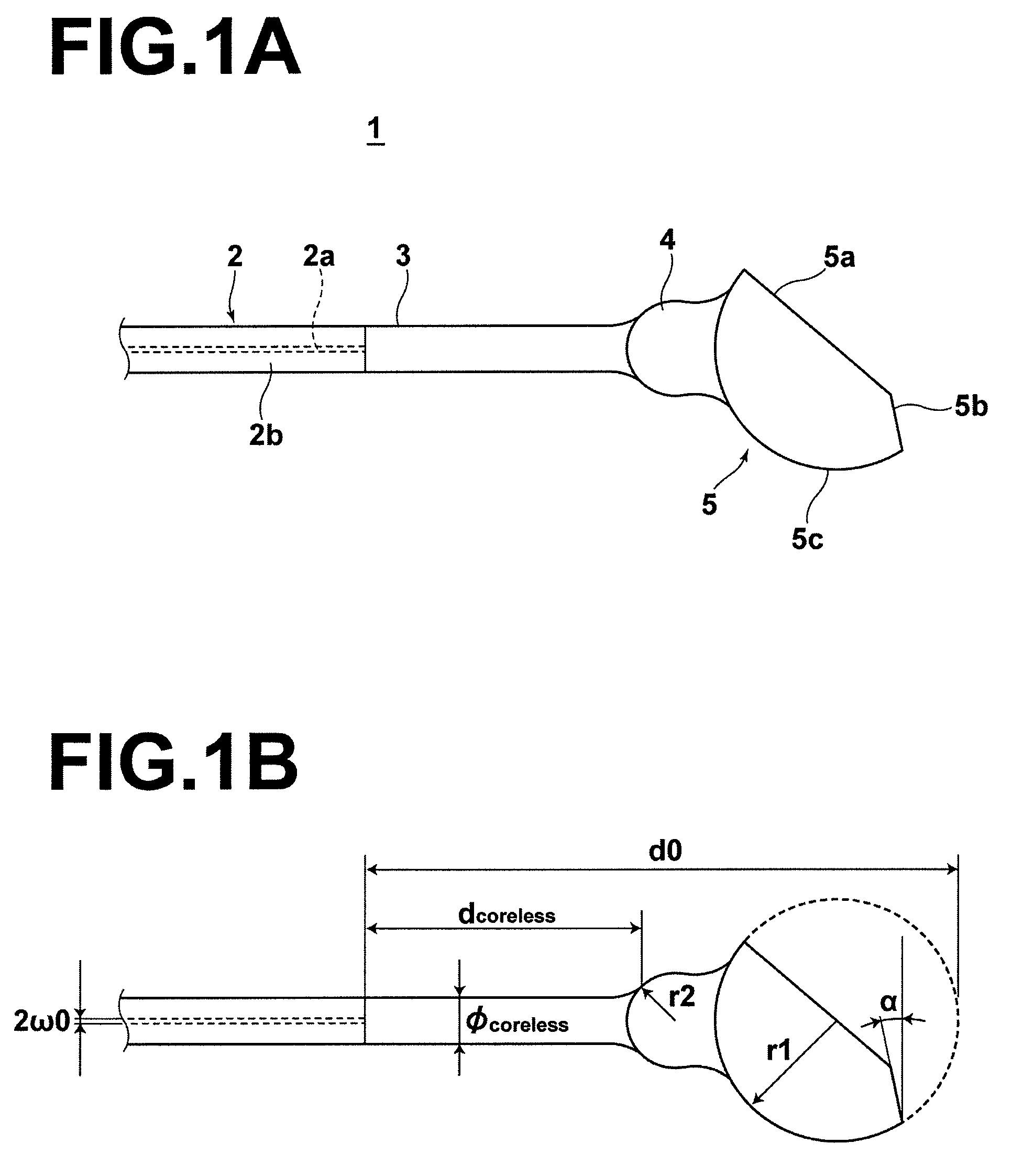
[0072]In the above formula, θ cut is the angle at which the reflecting surface 5a is formed with respect to the longitudinal axis of the second optical fiber 3. The light output angle θ out is determined by the reflecting surface forming angle θ cut, based on the above formula. Note that in the first embodiment, the light output angle θ out is set to approximately 7 degrees, for example.

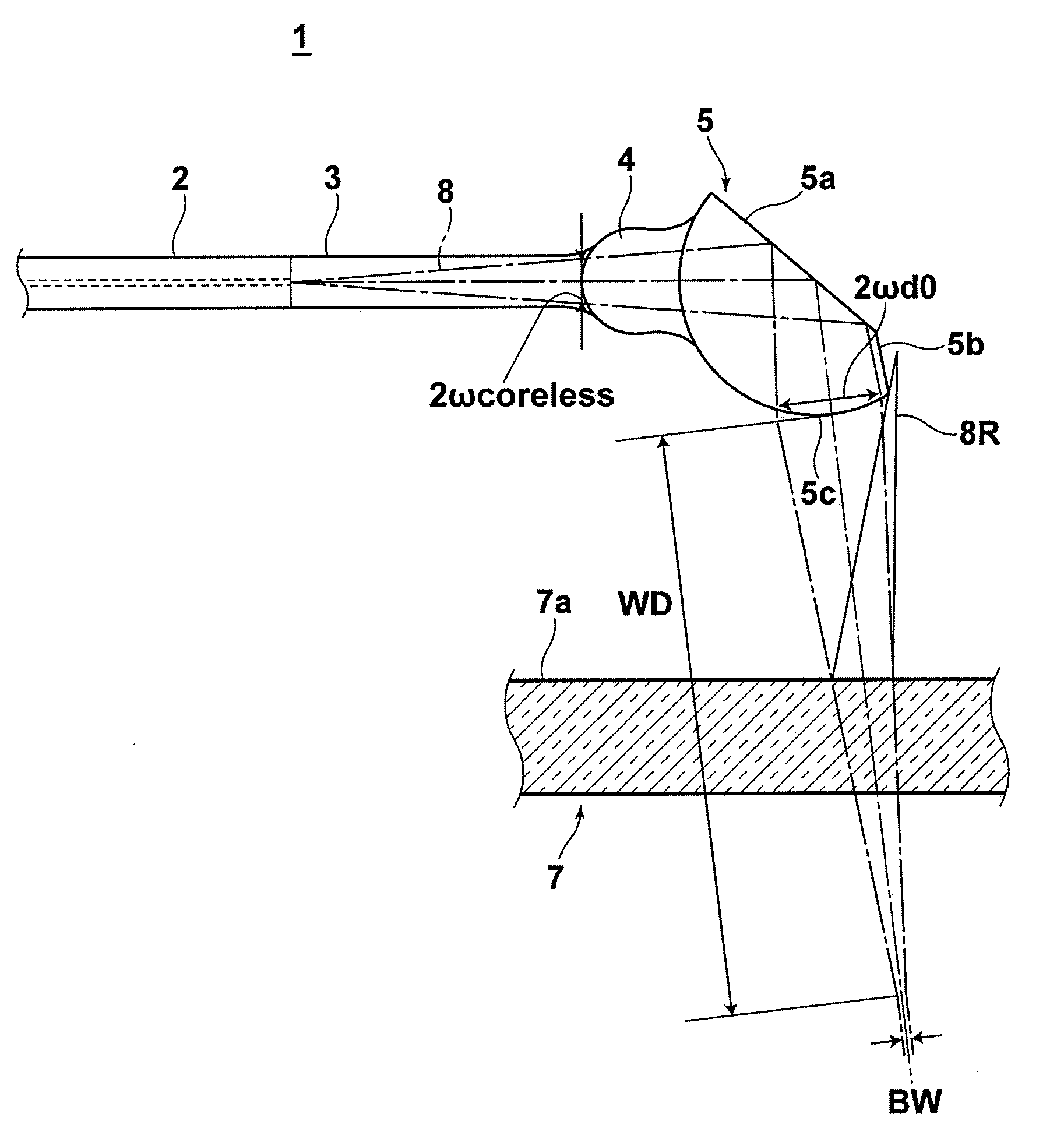
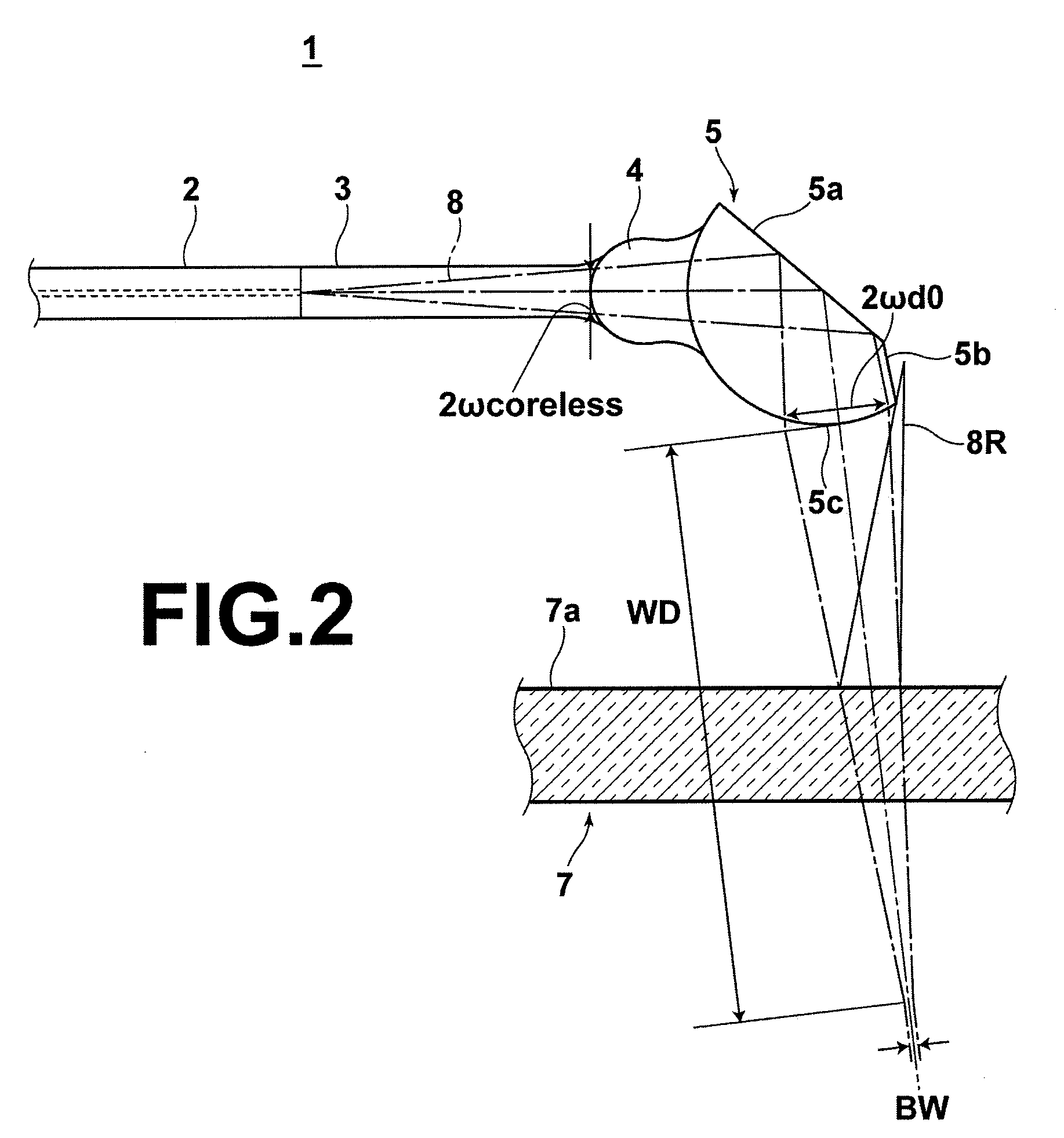
[0073]In addition, the beam radius ωdo (refer to FIG. 2) of the light beam at the light input / output surface 5c of the lens 5 can be derived by the Formula 4 below:

[0074]ω⁢⁢d⁢⁢0=ω⁢⁢0·1+(λ·d⁢⁢0π·n·ω2⁢0)2

wherein: ω0 is the core radius of the first optical fiber 2; λ is the wavelength of the light beam; n is the refractive index of the second optical fiber 3 with respect to the wavelength λ; and d0 is the distance that the light beam propagates from the end of the second optical fiber 3 to the lens 5.

[0075]Accordingly, the location at which the planar surface 5b is formed on the lens 5 is most preferabl...

second embodiment

[0099]Here, a light absorbing adhesive is employed as the adhesive 10. In the second embodiment, the adhesive 10 is employed as the reflected light sheath entrance preventing portion. Carbon black may be added to impart light absorbing properties to the adhesive 10. Because the outer periphery of the lensed optical fiber 1 is covered by the adhesive 10, even if the reflected light 8R, which is reflected at the inner surface 7a of the sheath 7 (refer to FIG. 7) enters the lensed optical fiber 1, the reflected light 8R is absorbed by the interface between the lensed optical fiber 1 and the adhesive 10. Accordingly, generation of ghost images is prevented.


PUM

PropertyMeasurementUnit
refractive indexaaaaaaaaaa
outer diameteraaaaaaaaaa

Abstract

An OCT probe has a sheath to be inserted into a subject; and an optical system within the sheath, for changing the direction of light which propagates from a light source through an optical fiber to irradiate the light onto the subject through a transparent portion of the sheath, and for reflecting the light beam, which is reflected by the subject, to guide the light into the optical fiber. A light output surface, for causing the light to be output from the reflecting surface in a direction obliquely inclined with respect to the inner surface of the sheath, and a reflected light sheath entrance preventing portion, for preventing light reflected by the inner surface of the sheath from entering the optical fiber, are provided in the optical system. The reflected light sheath entrance preventing portion may be formed by providing a cut planar surface portion on the lens.

Description

BACKGROUND OF THE INVENTION[0001]1. Field of the Invention[0002]The present invention is related to an apparatus for observing tomographic structures using light. Particularly, the present invention is related to a probe for observing tomographic structures within living organisms.[0003]2. Description of the Related Art[0004]The utilization of images during medical examinations is becoming widespread. Consequently, the importance of non invasive, non contact observation techniques is increasing.[0005]Conventionally, non invasive non contact observation and measurement of data within subjects such as living organisms had been performed by X rays. However, utilization of X rays has problems, such as the fact that subjects are irradiated with radiation, and that it is difficult to image the biological functions of the subjects. As a result, ultrasound endoscopic probes are in wide use for observation of tissue within body cavities. However, the spatial resolution of ultrasound endoscop...

Claims


Application Information

Patent Timeline
Patent Type & Authority Patents(United States)
IPC IPC(8): G02B6/00G02B6/26
CPCA61B5/0066A61B5/0073A61B5/6852G01N21/4795G02B6/327G02B6/2552
Inventor KATO, KIICHIMORIMOTO, YOSHINORIYAMAZAKI, HIROSHISAITO, MASAHIRO
Owner NAMIKI PRECISION JEWEL CO LTD
Why Eureka
Try Eureka