Method and apparatus for providing a bus interface with power management features

Active Publication Date: 2010-09-28
AVAGO TECH WIRELESS IP SINGAPORE PTE
View PDF2 Cites 27 Cited by
  • Summary
  • Abstract
  • Description
  • Claims
  • Application Information

AI Technical Summary

Problems solved by technology

Such bus interfaces may include complex circuitry including hundreds of thousands of logic gates.
As device geometries (e.g., transistor channel lengths) in advanced semiconductor manufacturing processes continue to shrink (e.g., to 90 nm and smaller), leakage current becomes a much larger component of the overall power consumption of circuits implemented using such processes.
With such increases in leakage current, it may be difficult or impossible to meet power cons

Method used


Image

  • Method and apparatus for providing a bus interface with power management features
  • Method and apparatus for providing a bus interface with power management features
  • Method and apparatus for providing a bus interface with power management features

Examples


example pci

Express Bus Interfaces

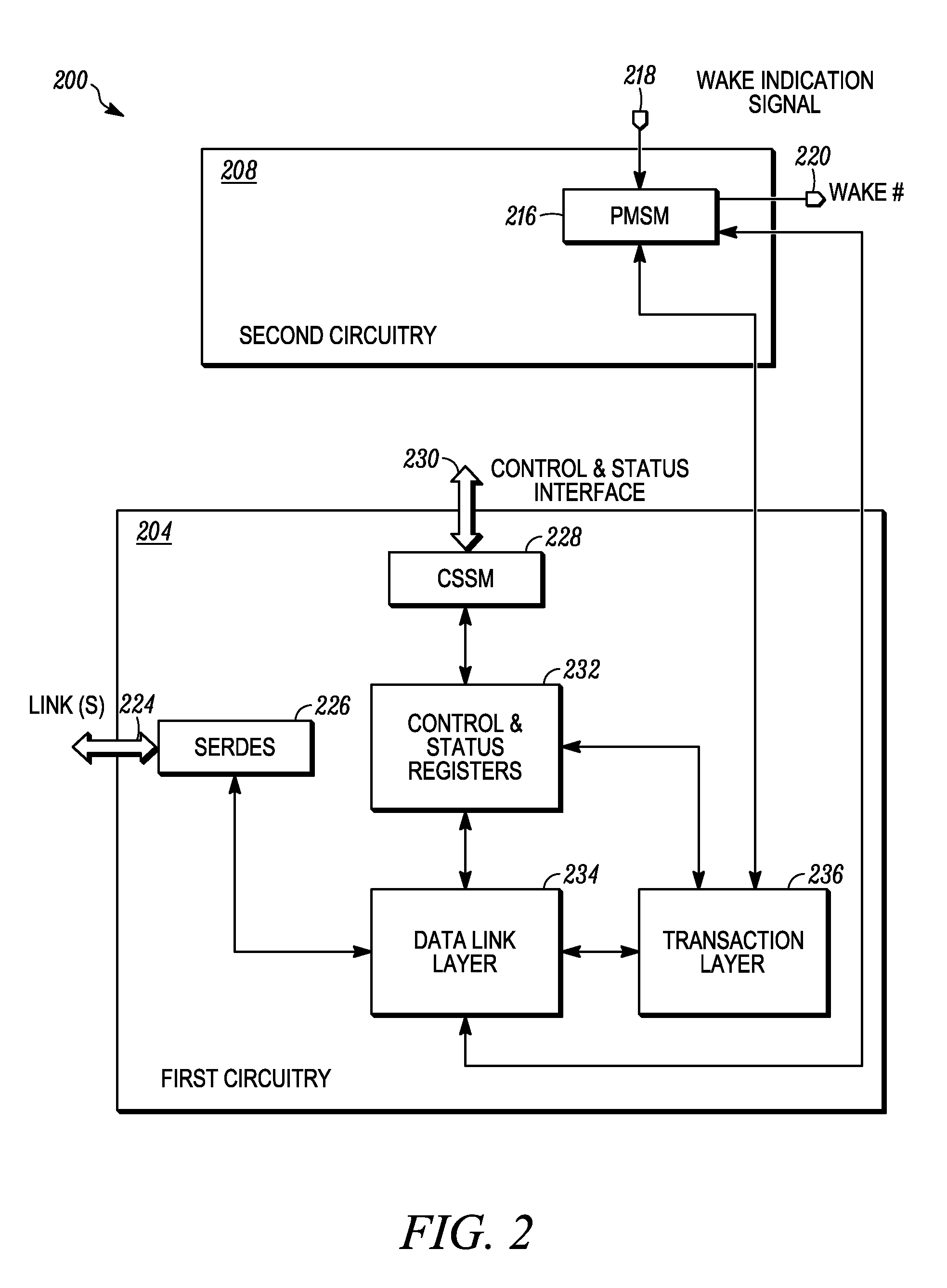
[0036]FIG. 2 is a schematic block diagram of an example embodiment of a bus interface 200 implemented in accordance with the PCIE protocol. The PCIE protocol is known and will not be described in detail here. The PCIE protocol specifications are available from the PCI Special Interest Group (PCI-SIG), 3855 SW 153rd Drive, Beaverton, Oreg. 97006.

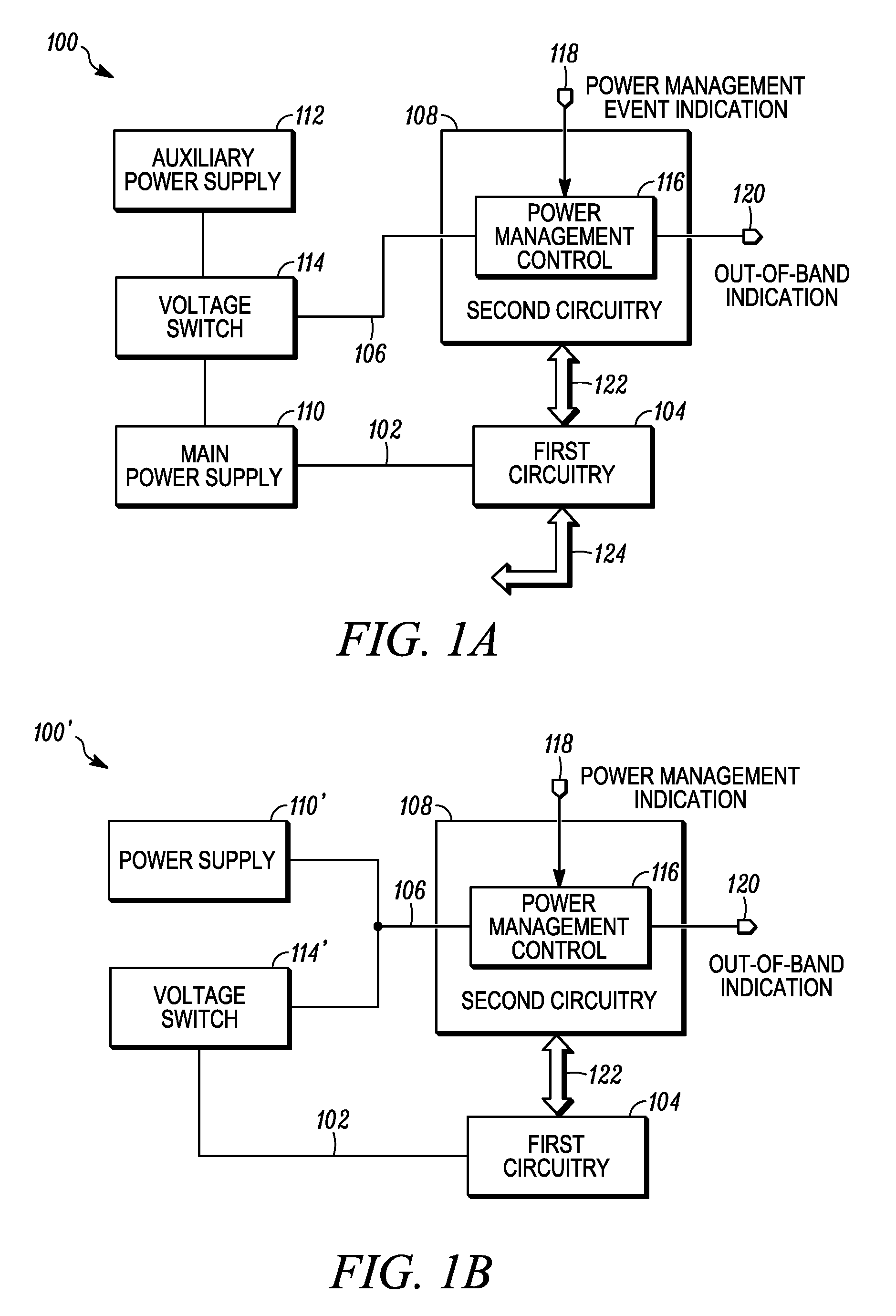
[0037]The bus interface 200, in similar fashion to the bus interfaces 100 and 100′, includes first circuitry 204 and second circuitry 208. The first circuitry 204 and the second circuitry 208 may be provided with power as was described above with respect to FIGS. 1A and 1B. Alternatively, power may be applied to the first circuitry 204 and the second circuitry 206 in any other appropriate fashion that allows for providing power to the first circuitry 204 in a normal operating mode and removing power from the first circuitry 204 in a low power operating mode, while providing power to the second circuitry in both the norma...

example method

for Providing a Bus Interface

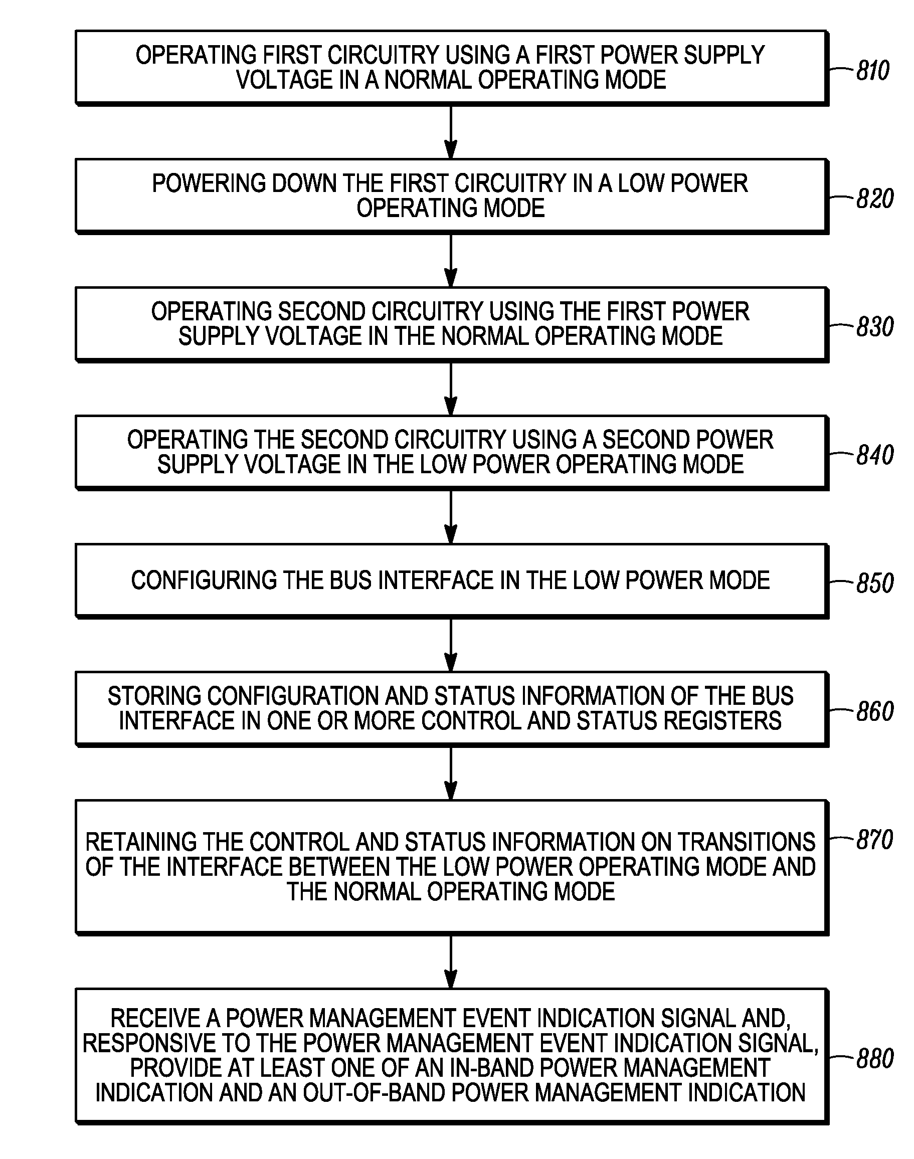
[0063]FIG. 8 is a flowchart of an example method 800 for providing a bus interface. The method 800 may be implemented, for example, in the bus interfaces described herein. The method 800 includes, at block 810, operating first circuitry using a first power supply voltage in a normal operating mode. In the method 800 the first circuitry may include at least a portion of datapath circuitry of the bus interface. At block 820, the method 800 includes powering down the first circuitry in a low power operating mode, such as described above. At block 830, the method 800 includes operating second circuitry using the first power supply voltage in the normal operating mode. At block 840, the method 800 includes operating the second circuitry using a second power supply voltage in the low power operating mode.

[0064]The method 800 further includes, at block 850, configuring the bus interface in the low power mode, at block 860, storing configuration and status infor...


PUM


Abstract

Methods and apparatus for providing a bus interface are disclosed. An example method for providing a bus interface includes operating first circuitry using a first power supply voltage in a normal operating mode, where the first circuitry includes at least a portion of datapath circuitry of the bus interface. The example method further includes powering down the first circuitry in a low power operating mode and operating second circuitry using the first power supply voltage in the normal operating mode. The example method also includes operating the second circuitry using a second power supply voltage in the low power operating mode. The second circuitry includes a power management control circuit adapted to receive a power management event indication signal. Responsive to the power management event indication signal, the control circuit provides at least one of an in-band power management indication and an out-of-band power management indication to one or more devices in a computing system. In the example method, the first and second power supply voltages may be provided by a single power supply or, alternatively, by multiple power supplies.

Description

BACKGROUND[0001]Bus interfaces are used in numerous electronic devices and systems to communicate data from one device to another. For instance, a network interface card may include a bus interface that communicates data (e.g., parallel and / or serial data) with any number of other devices, such as a computer motherboard or system memory, for example. There are a wide range of bus interface protocols and corresponding bus interfaces (e.g., circuits and / or logic) that are implemented in accordance with those bus interface protocols. Some examples of such protocols include the Peripheral Component Interconnect (PCI) protocol, the PCI Express (PCIE) protocol, the Universal Serial Bus (USB) protocol, the HyperTransport protocol and the InfiniBand protocol, among numerous other protocols.[0002]Such bus interfaces may include complex circuitry including hundreds of thousands of logic gates. In certain cases, it may be desirable, at times, to operate a bus interface in a low power mode wher...

Claims


Application Information

Patent Timeline
IPC IPC(8): G06F1/00G06F1/26G06F1/32
CPCG06F1/3203G06F1/3253Y02B60/1235Y02B60/32Y02D10/00Y02D30/50
Inventor KENDALL, CHADMCDANIEL, SCOTTPULIKKAL, SUNIL
Owner AVAGO TECH WIRELESS IP SINGAPORE PTE
Why Eureka
Try Eureka