Exhaust emission purifying apparatus for engine

a technology of exhaust gas purification apparatus and purifying apparatus, which is applied in mechanical apparatus, machines/engines, separation processes, etc., can solve the problems of water scale accumulation on the pipe wall, inability to and inability to achieve smooth injection of reducing agen

Active Publication Date: 2010-10-05
VOLVO TRUCK CORP
View PDF52 Cites 21 Cited by
  • Summary
  • Abstract
  • Description
  • Claims
  • Application Information

AI Technical Summary

Benefits of technology

[0008]Therefore, it is an object of the present invention to prevent a reducing agent from being frozen or to defrost a frozen reducing agent by employing cooling water of an engine as a heating medium, and also to prevent water scale from being accumulated, due to residence of the cooling water, on a cooling water pipe for leading the cooling water to a reducing agent tank.
[0010]According to the present invention, by heating a reducing agent in a reducing agent tank by a heating device using cooling water of an engine, as a heating medium, the reducing agent can be prevented from being frozen or the frozen reducing agent can be defrosted. Further, by opening the cutoff valve for a predetermined period after start of the engine, the cooling water can be periodically circulated in the cooling water pipe and accumulation of water scale can be prevented.

Problems solved by technology

However, the exhaust emission purifying apparatus storing a reducing agent in a solution state has the following problem.
Until the reducing agent is completely defrosted, smooth injection of the reducing agent cannot be performed.
Consequently, when the heating is not performed for a long time in a case such that the vehicle is moved out from the cold area, there is the possibility that the cooling water remains in the pipe and water scale accumulates on the pipe wall.

Method used


Image

  • Exhaust emission purifying apparatus for engine
  • Exhaust emission purifying apparatus for engine
  • Exhaust emission purifying apparatus for engine

Examples


Embodiment Construction

[0017]An embodiment of the present invention will be described hereinbelow with reference to the drawings.

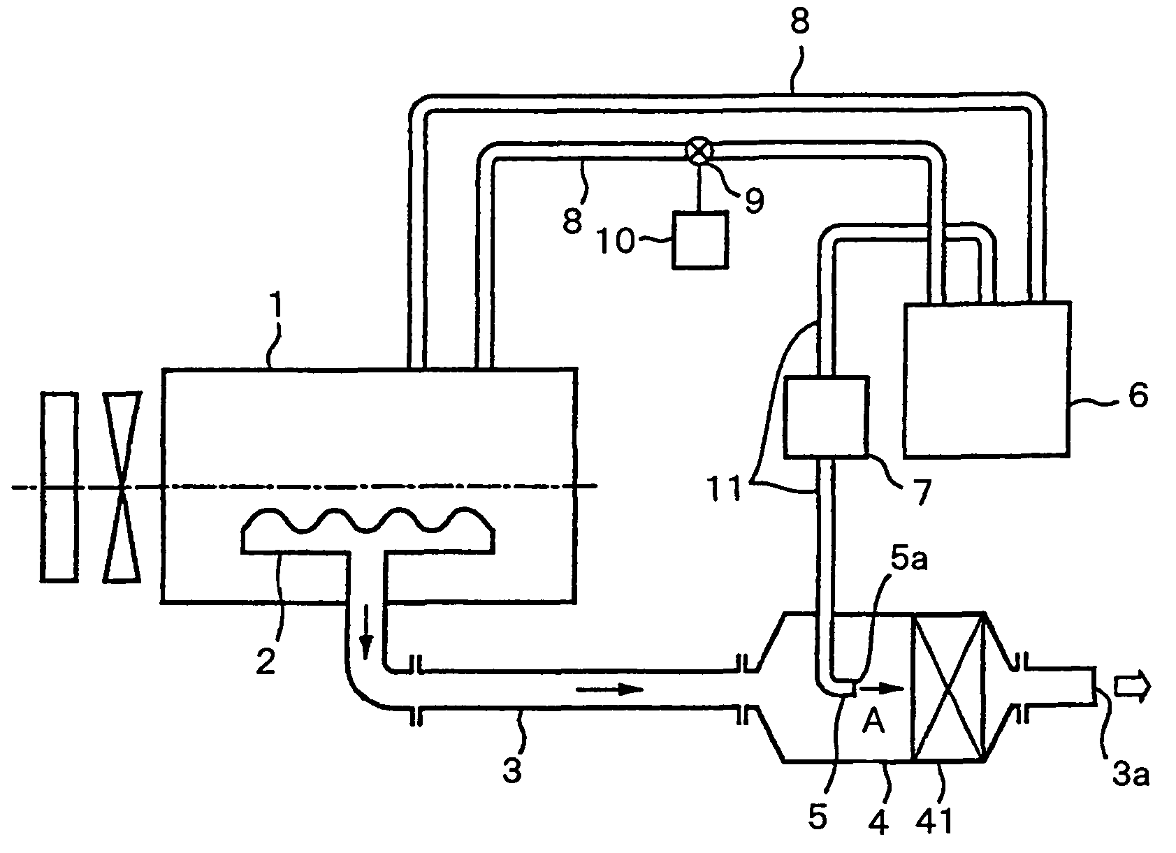
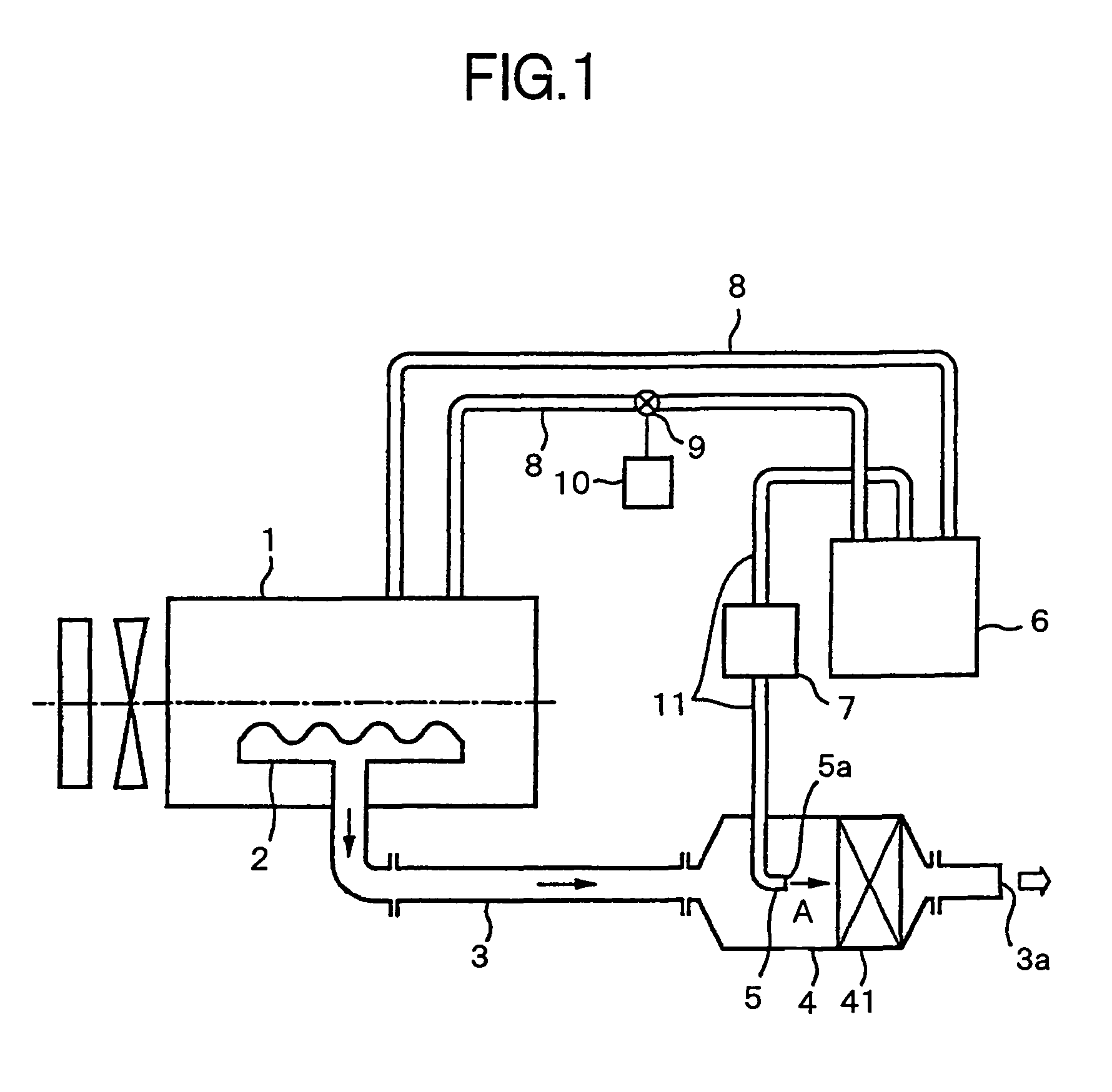
[0018]FIG. 1 shows the configuration of an exhaust emission purifying apparatus for an engine according to one embodiment of the invention. The exhaust emission purifying apparatus reduces NOx exhausted from an on-vehicle engine 1 (concretely, diesel engine, simply called “engine” hereinbelow) in post treatment. An exhaust pipe 3 is connected to an exhaust manifold 2 of the engine 1, and the exhaust gas of the engine 1 is released to the atmosphere via the exhaust manifold 2 and the exhaust pipe 3.

[0019]A catalyst container 4 is interposed in the exhaust pipe 3 near a discharge port 3a, and a reduction catalyst 41 is housed in the catalyst container 4. The reduction catalyst 41 is a monolithic-type catalyst formed by making zeolite-based active ingredients carried on a honeycomb integral molding carrier made of cordierite as ceramic or Fe—Cr—Al-based heat-resisting steel. The ac...


PUM

PropertyMeasurementUnit
temperatureaaaaaaaaaa

Abstract

The present invention is directed to defrost a reducing agent with cooling water of an engine and to prevent water scale from being deposited and accumulated on a cooling water pipe for circulating the cooling water. A frozen reducing agent is defrosted by being heated with cooling water of an engine. A cooling water pipe for guiding the cooling water to a reducing agent tank is provided with a cutoff valve. To defrost the reducing agent, the cutoff valve is opened. Even in the case where the reducing agent is not frozen, the cutoff valve is opened for a predetermined period after start of the cutoff valve to circulate the cooling water in the cooling water pipe.

Description

[0001]This application is a continuation of PCT / JP2005 / 17287, filed on Sep. 20, 2005.BACKGROUND OF THE INVENTION[0002]1. Field of the Invention[0003]The present invention relates to an exhaust emission purifying apparatus for an engine. More particularly, in such one having a given configuration such that a reducing agent to be added to an exhaust gas in the exhaust emission in order to reduce nitrogen oxides, is stored in a solution state in a reducing agent tank, the invention relates to a technique of heating the reducing agent in the reducing agent tank with cooling water of an engine to prevent the reducing agent from being frozen or to defrost the frozen reducing agent, and also relates to a technique of preventing the cooling water from residing in a cooling water pipe for leading the cooling water to the reducing agent tank so that water scale is not deposited on the pipe wall.[0004]2. Description of the Related Art[0005]As an apparatus for purifying nitrogen oxides (hereinb...

Claims


Application Information

Patent Timeline
Patent Type & Authority Patents(United States)
IPC IPC(8): F01N3/00B01D53/94F01N3/20F01N3/08F01N3/28
CPCB01D53/9431F01N11/00B01D2251/2067F01N3/208F01N2550/05F01N2610/02F01N2610/10F01N2610/14F01N2900/08F01N2900/1811Y02T10/47Y02T10/40
Inventor SATOU, HIROKAZUNISHINA, MITSUHIRO
Owner VOLVO TRUCK CORP
Why Eureka
Try Eureka