
Thermal recovery of petroleum crude oil from tar sands and oil shale deposits

a technology of petroleum crude oil and tar sands, which is applied in the direction of hydrocarbon oil cracking process, packaging, chemical/physical/physicochemical process, etc., can solve the problems of increasing costs and achieve the effect of eliminating all possible contamination

Inactive Publication Date: 2010-10-05
COLLETTE JERRY R
View PDF6 Cites 59 Cited by
  • Summary
  • Abstract
  • Description
  • Claims
  • Application Information

AI Technical Summary

Benefits of technology

"The present invention provides a new and unique approach to dry thermal processing that eliminates the need for water, steam, and solvents. The system uses a series of graduated heated containers and heated augers or thermal screws to elevate material temperature in gradual stages using conductive heat transfer from hot surface contact. The process is efficient, safe, and meets all environmental requirements for air, water, and soil. The material can be used for various purposes such as agriculture, backfilling, and recreational development. The system is designed for any throughput rate desired and can be transported and assembled on-site. The thermal screws are heated by direct contact with a heated fluid and pumped through the hollow blades and auger jacket to elevate material temperature. The system is designed to process tar sand and is the only one of its kind that meets all environmental requirements."

Problems solved by technology

Since tar sands tend to re-agglomerate rather quickly after stockpiling, it is best to mill only sufficient material to keep the process system fed at the hourly throughput rate.
Pre mining and stockpiling of material for more than one day requires rehandling of agglomerated material, elevating costs.

Method used


Image

  • Thermal recovery of petroleum crude oil from tar sands and oil shale deposits
  • Thermal recovery of petroleum crude oil from tar sands and oil shale deposits
  • Thermal recovery of petroleum crude oil from tar sands and oil shale deposits

Examples


Embodiment Construction

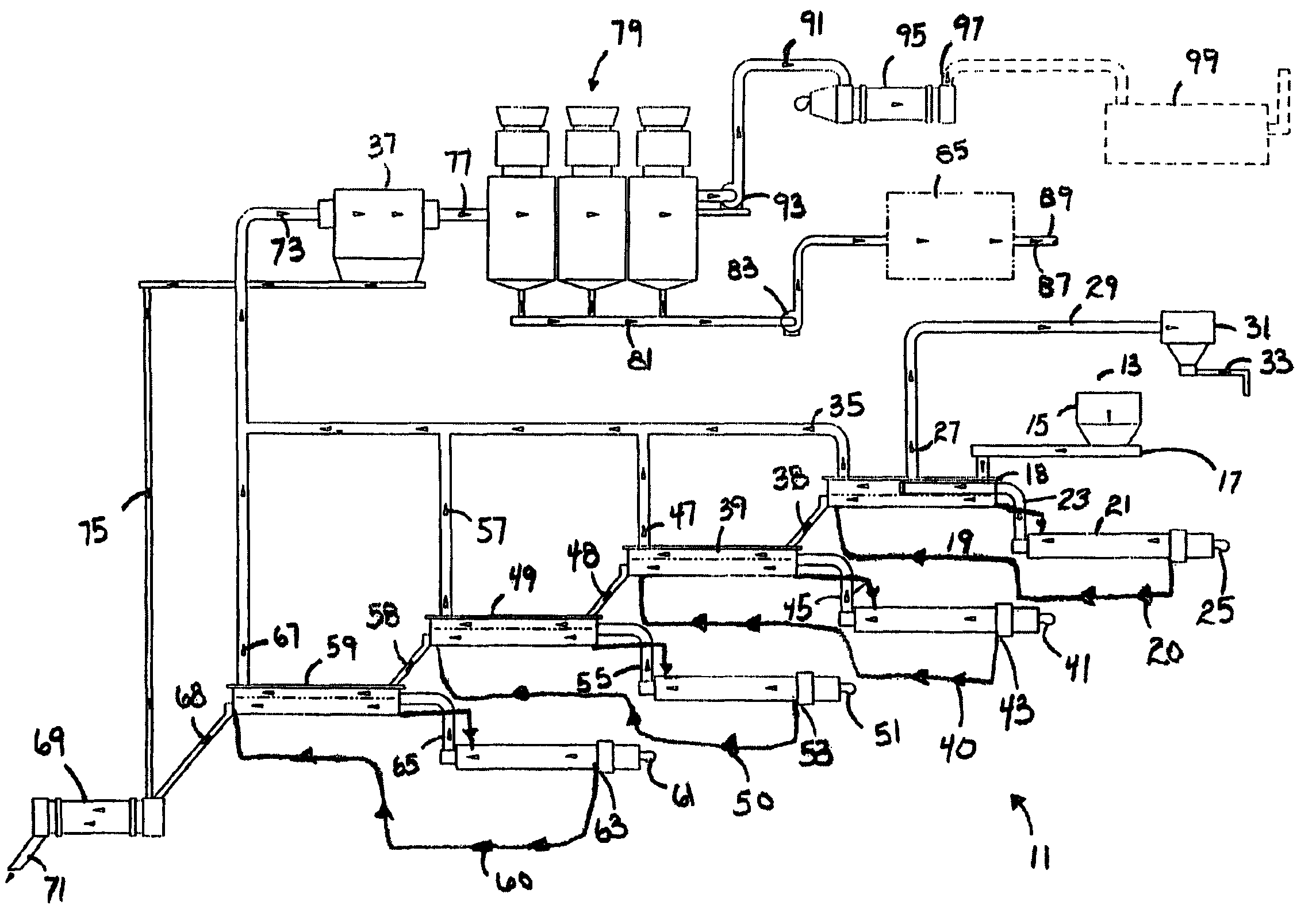
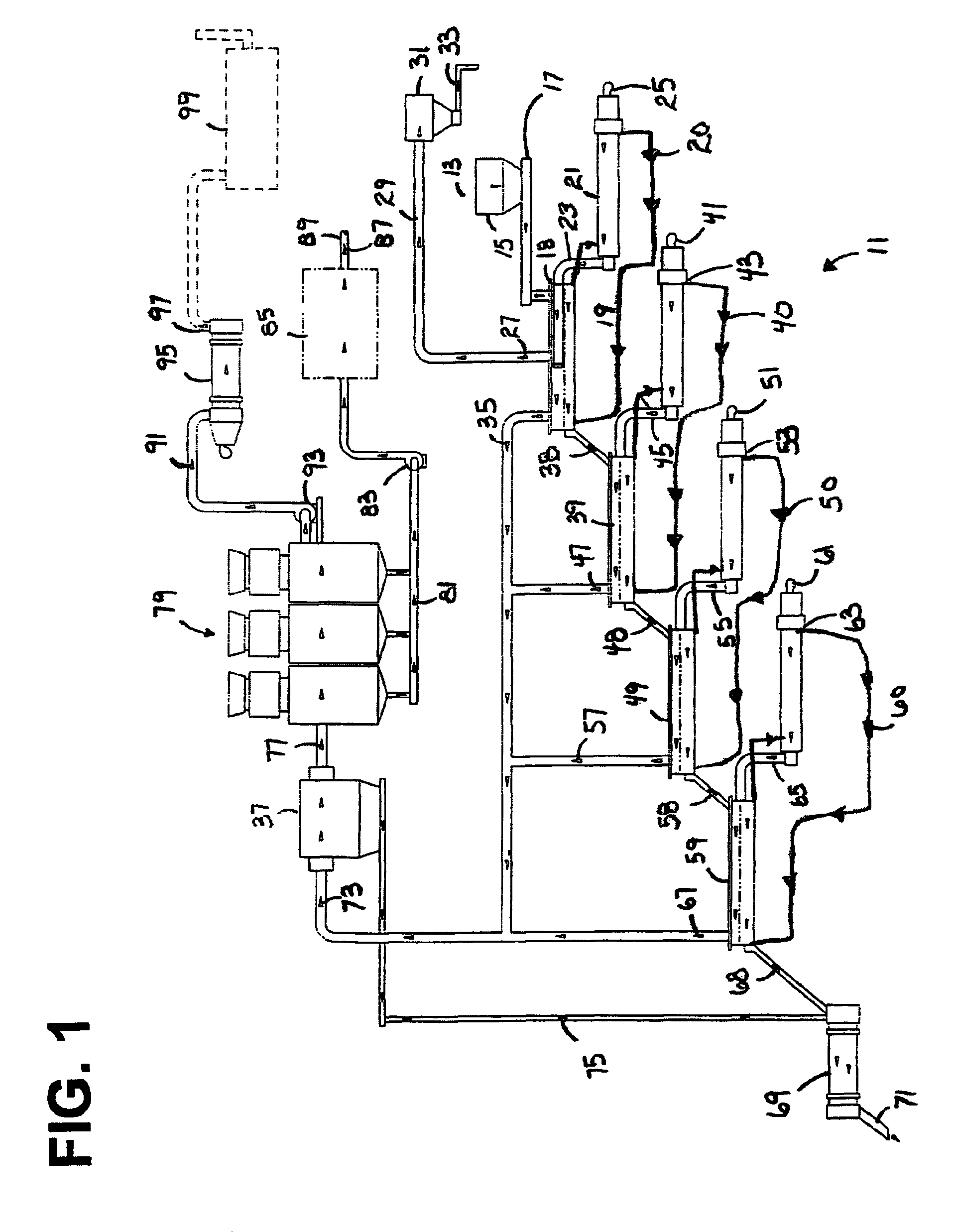
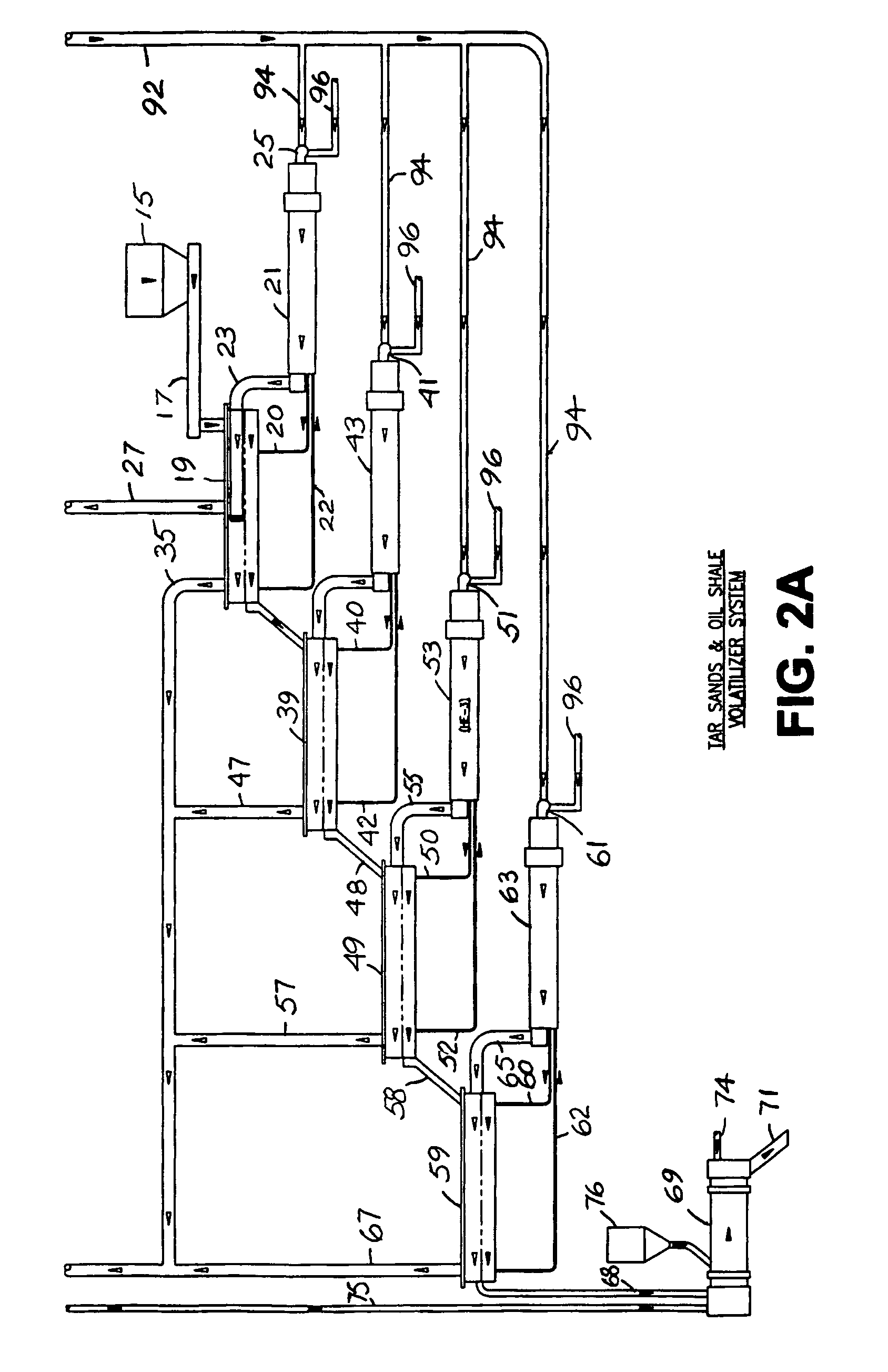
[0040]FIGS. 1 and 2A and 2B are schematic representations of the thermal recovery system 11. The thermal recovery system 11 shown in FIGS. 1 and 2A and 2B are examples of embodiments of the present invention. Other sizes and configurations are possible. In an illustrative example, approximately 208 tons of sand are processed per hour at approximately 5,000 tons / day. Tar sand input moisture content is approximately 2%. Sand inlet temperatures are approximately 60° F. and sand exit temperatures are approximately 950° F.

[0041]Raw oil-bearing sand 13 is dumped into a hopper 15. The raw sand 13 in hopper 15 is fed through a conveyor 17 at a predetermined flow rate. The raw sand 13 is conveyed into the first indirectly heated end 18 of a first auger conveyor 19. A first heat exchanger 21 with a first burner 25 heats a first heating fluid 20 to approximately 650° F. The first heat exchanger 21 also creates a first exhaust gas 23 at approximately 650° F., which is used as a sweep gas. The b...


PUM

PropertyMeasurementUnit
temperatureaaaaaaaaaa

Abstract

A tar sand volatilizer system thermally removes petroleum crude oil from tar sands or shale oil. A series of heated augers or thermal screws are used to elevate material temperature gradually using conductive heat transfer. The thermal screws blades and auger case receive a heated fluid. The screws are driven by variable speed drive systems. The unit is sized for any throughput rate desired. Hot clean material discharges into a rotary cooler and re-hydrator unit. The exhaust gases are pulled through a high temperature filter collector for particulate removal. The particulate free petroleum vapor laden hot gas exits the filter house into a multi stage condenser system with water chillers where the vapor temperature is gradually cooled. A microwave upgrader system processes crude oil using catalyst injected microwave technology to produce a diesel like fuel oil in a continuous process stream.

Description

[0001]This application claims the benefit of U.S. Provisional Application No. 60 / 771,447, filed Feb. 9, 2006, which is hereby incorporated by reference in its entirety.TECHNICAL FIELD OF THE INVENTION[0002]The present invention relates to the field of thermal recovery of petroleum crude oil from deposits of sand and shale.BACKGROUND OF THE INVENTION[0003]Processes are needed for the thermal recovery of petroleum crude oil from deposits of sand and shale that lie on or near the earth's surface in many parts of the world.[0004]The true amount of reserves located throughout the world is not known. However, it is estimated that there are at least 30 billion barrels within tar sand and oil shale deposits in the United States alone. These reserves remain as yet un-tapped sources of valuable crude oil that does not require drilling and deep well recovery techniques. Petroleum laden sand and shale deposits are generally positioned on or near the surface of the ground and lay in horizontal l...

Claims


Application Information

Patent Timeline
Patent Type & Authority Patents(United States)
IPC IPC(8): C10G1/00
CPCC10B47/44C10B53/06C10B57/02C10G1/02C10G15/08C10G32/02
Inventor COLLETTE, JERRY R.
Owner COLLETTE JERRY R
Learn More