
High-efficiency envelope tracking systems and methods for radio frequency power amplifiers

a technology of high-efficiency envelope tracking and radio frequency power amplifier, applied in process and machine control, ignition automatic control, instruments, etc., can solve the problems of linear rfpas inefficient, linear rfpas sacrifice efficiency for linearity, and high undesirable efficiency versus linearity trade-off, etc., to reduce efficiency penalty

Active Publication Date: 2010-10-05
INTEL CORP
View PDF4 Cites 30 Cited by
  • Summary
  • Abstract
  • Description
  • Claims
  • Application Information

AI Technical Summary

Benefits of technology

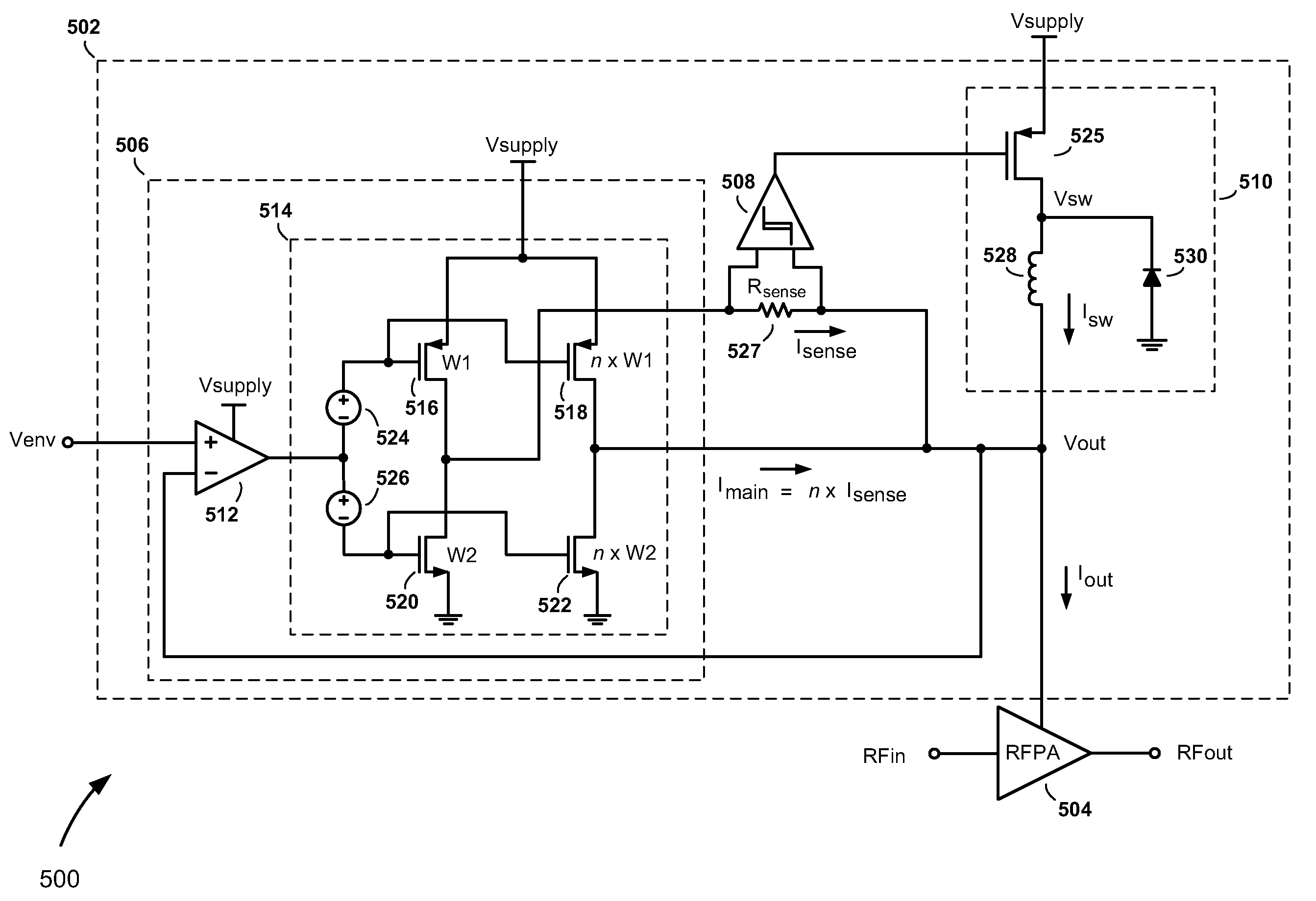
[0015]A current sense path connected in parallel with the main current path includes a current sense resistor used by a hysteresis comparator to control the switching of the switch-mode converter. The split-path linear regulator is configured so that current flowing in the current sense path is a lower, scaled version of the current flowing in the main current path. By permitting only the lower, scaled version to flow through the sense resistor, the current sense resistor can be made larger than is required in prior art approaches, and without a distortion or reduction in efficiency penalty.

Problems solved by technology

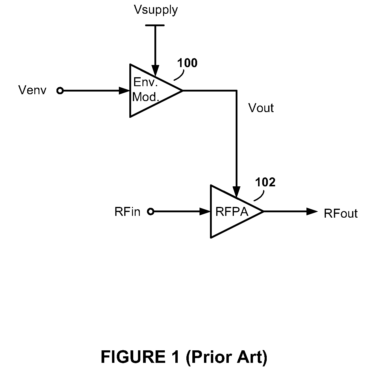
However, because linear RFPAs are not very power efficient, the requirement of a linear RFPA results in a sacrifice of efficiency for linearity.
This efficiency versus linearity trade-off is highly undesirable, particularly when the transmitter is employed in battery-powered applications such as in a wireless handset or a wireless network interface card of portable computer.
Not only are linear RFPAs inefficient, they are also usually the dominant consumer of power in a transmitter.
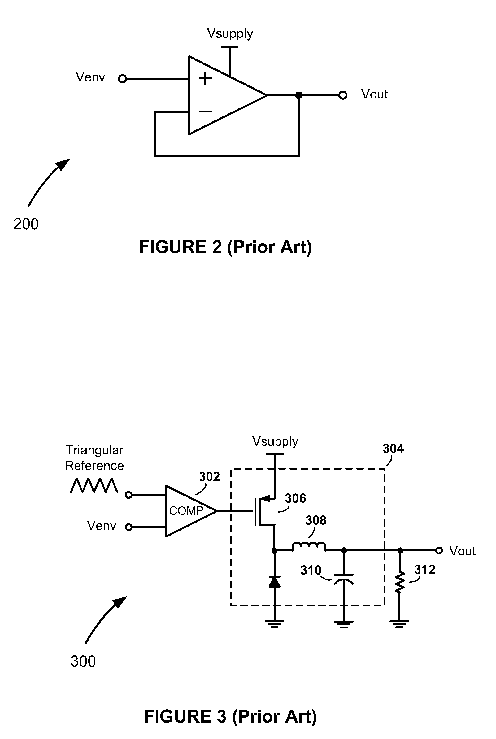
However, a significant drawback of the linear regulator 200 is that it is inefficient for input signal amplitudes that are lower than the magnitude of the DC supply voltage Vsupply.
This inefficiency increases as the voltage difference between the input signal and DC supply voltage Vsupply widens.
This switching noise can make it difficult to comply with noise limitation requirements imposed by communications standards.
However, because the signal envelope bandwidth of wide bandwidth applications is often 1 MHz or higher, switch-mode converters are not well-suited for generating dynamic power supply signals in wideband applications.
However, this results in degraded efficiency.
Unfortunately, a resistance of this value, which is both accurate and reproducible, is very difficult to realize using standard semiconductor fabrication processes.

Method used


Image

  • High-efficiency envelope tracking systems and methods for radio frequency power amplifiers
  • High-efficiency envelope tracking systems and methods for radio frequency power amplifiers
  • High-efficiency envelope tracking systems and methods for radio frequency power amplifiers

Examples


Embodiment Construction

[0025]Referring to FIG. 5, there is shown an envelope tracking (ET) system 500, according to an embodiment of the present invention. The ET system 500 comprises an envelope modulator 502 and a radio frequency power amplifier (RFPA) 504. The RFPA 504 includes an RF input configured to receive an RF input signal RFin, an RF output configured to provide an RF output signal RFout, and a power supply input configured to receive a dynamically controlled power supply voltage Vout from an output node of the envelope modulator 502.

[0026]The dynamic power control methods and apparatus of the present invention can be used in envelope elimination and restoration (EER) type systems employing nonlinear RFPAs, such as a polar transmitter, as well as in ET type systems employing linear RFPAs. Because the envelope of the input signal envelope is tracked in both EER and ET approaches, the term “envelope tracking” (including its abbreviated form “ET”) is used herein in its most general sense to refer ...


PUM


Abstract

High-efficiency envelope tracking (ET) methods and apparatus for dynamically controlling power supplied to radio frequency power amplifiers (RFPAs). An exemplary ET circuit includes a switch-mode converter coupled in parallel with a split-path linear regulator. The switch-mode converter is configured to generally track an input envelope signal Venv and supply the current needs of a load (e.g., an RFPA). The split-path linear regulator compensates for inaccurate envelope tracking by sourcing or sinking current to the load via a main current path. A current sense path connected in parallel with the main current path includes a current sense resistor used by a hysteresis comparator to control the switching of the switch-mode converter. The split-path linear regulator is configured so that current flowing in the current sense path is a lower, scaled version of the current flowing in the main current path.

Description

FIELD OF THE INVENTION[0001]The present invention relates generally to controlling the delivery of power to radio frequency power amplifiers (RFPAs). More specifically, the present invention relates to high-efficiency envelope tracking (ET) systems and methods for controlling and supplying power to RFPAs.BACKGROUND OF THE INVENTION[0002]In an effort to satisfy consumer demand for faster data rates, while at the same time striving to use the radio frequency spectrum most efficiently, many modern wireless communications technologies employ non-constant-envelope modulation formats. For example, 802.11g (or “Wi-Fi”) wireless local area network (WLAN) technology employs orthogonal frequency-division multiplexing (OFDM), which is non-constant envelope modulation format. Third generation (3G) wideband code division multiple access (W-CDMA) cellular technology employs quadrature phase shift keying (QPSK), which is also a non-constant envelope modulation format. Other and future technologies...

Claims


Application Information

Patent Timeline
Patent Type & Authority Patents(United States)
IPC IPC(8): H03F3/04
CPCG05F1/565H03F1/0222H03F3/195H03F3/24H02M2001/0045H03F2200/451H03F2200/456H03F2200/462H03F2200/481H02M1/0045
Inventor TAKINAMI, KOJILIANG, PAUL CHENG-PO
Owner INTEL CORP
Learn More