Antiglare light diffusing member and method for producing same, and display

a technology of diffusing member and light, applied in the direction of diffusing elements, optical elements, instruments, etc., can solve the problems of inconvenient adjustment, inconvenient adjustment, and inability to adjust easily

Active Publication Date: 2010-10-19
TOPPAN PRINTING CO LTD
View PDF19 Cites 6 Cited by
  • Summary
  • Abstract
  • Description
  • Claims
  • Application Information

AI Technical Summary

Benefits of technology

[0077]The present invention aims to provide an antiglare light diffusing member using internal diffusion and surface diffusion in combination, wherein a surface haze value mainly representing the degree of surface diffusion and an internal haze value mainly representing the degree of internal diffusion are easily adjusted independently from each other.

Problems solved by technology

Displays such as a liquid crystal display, CRT display, EL display and plasma display have some problems described below from the viewpoint of visibility.External light reflects at looking and listening.Surface glare (scintillation) occurs at the display surface by display light from the display.Visibility is not good caused by dazzle of display light directly coming from the display without being diffused, etc.Visibility is also degraded by such defect as unevenness of brightness.
However, when there is a defect or an adhered foreign substance on an emboss roll, endless defects occurs at the pitch of roll.
Consequently, in the case of mass production, all the products have defect.
Further, since the scattering only at the surface is utilized, there are following problems.Abrasion resistanceLowering of contrastOccurrence of dazzling
However, there is such problem in the methods that the sharpness of a transmitted image is lowered.
However, there are following problems.Lowering of contrastOccurrence of dazzling caused by lens effect of the surface irregularityLowering of abrasion resistance
The combined use of internal scattering and surface scattering leads to smaller surface irregularity compared with an antiglare light diffusing member using surface scattering alone.
Therefore, there are many factors to be limited such as the thickness.
Controlling the surface haze, internal haze etc. in a limited range is difficult.
Therefore, setting to an intended surface haze and internal haze is difficult.
For example, when lowering the surface haze without altering the internal haze, the control by the addition amount of particles alone is impossible.
Even in the following cases where plural types of particles are used, setting to intended surface haze and internal haze is difficult.A case where particles having identical refraction indices and being different only in particle sizes are used.A case where refraction indices of all the particles are different from refraction index of resin to some extent.

Method used


Image

  • Antiglare light diffusing member and method for producing same, and display
  • Antiglare light diffusing member and method for producing same, and display

Examples


example 1a

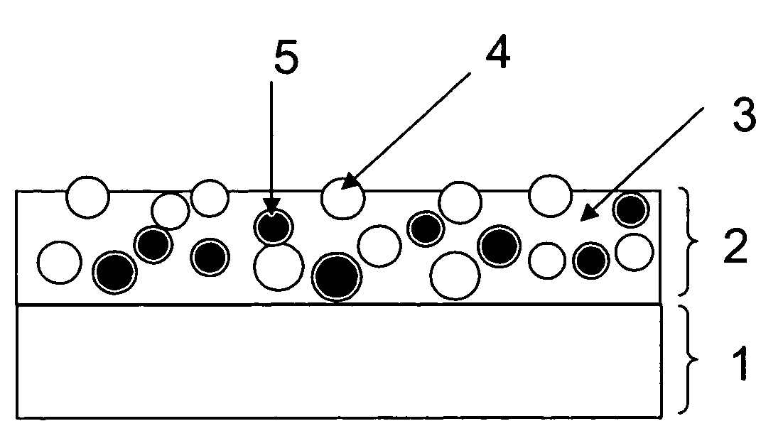
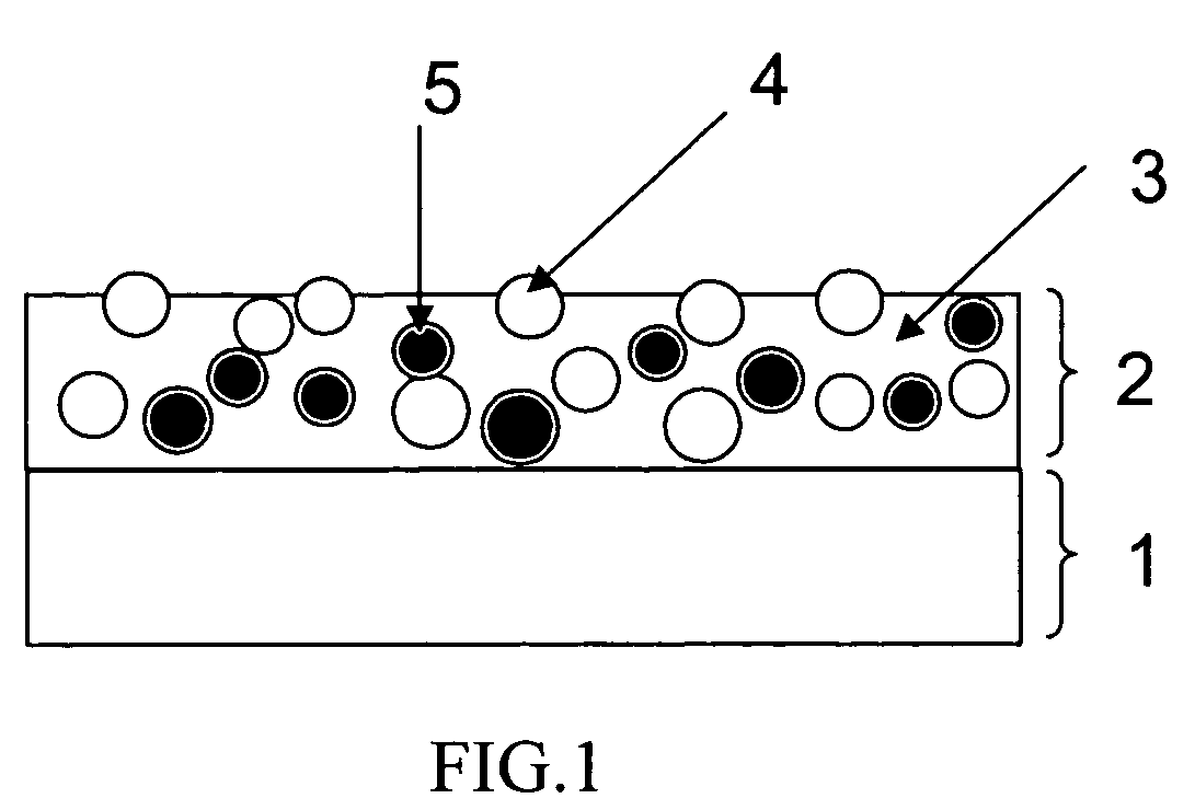
[0162]A triacetylcellulose film (TD-80U manufactured by Fuji Photo Film Co., LTD.; refraction index 1.49, film thickness 80 μm) was used as abase material. On the base material, an antiglare light scattering coating liquid having the composition shown in Table 1 was coated with a slot die coater. Then, a solvent included in the coating liquid was evaporated. Then, the antiglare light scattering layer was cured through ultraviolet irradiation of 400 mJ using a high-pressure mercury lamp under an atmosphere of 0.03% or less of oxygen concentration. The dried antiglare light scattering layer had a thickness of 6.0 μm. Thus, a sample was prepared.

[0163]Here, a measuring method of the refraction index of a binder matrix is described below. A coating liquid similar to that described above was prepared. But, no particle was contained in the coating liquid. The coating liquid was coated, dried and cured according to a method similar to that described above. The refraction index of thus obta...

example 1b

[0166]An antiglare light scattering coating liquid having the composition shown in Table 1 was used. An antiglare light scattering layer was prepared in the same way as in Example 1A except for the type of the antiglare light scattering coating liquid.

[0167]The refraction index of the binder matrix, refraction index of the particle and average particle size of the particle were measured in the same way as in Example 1A.

example 1c

[0168]An antiglare light scattering coating liquid having the composition shown in Table 1 was used. An antiglare light scattering layer was prepared in the same way as in Example 1A except for the type of the antiglare light scattering coating liquid.

[0169]The refraction index of the binder matrix, refraction index of the particle and average particle size of the particle were measured in the same way as in Example 1A.


PUM

PropertyMeasurementUnit
internal hazeaaaaaaaaaa
particle sizeaaaaaaaaaa

Abstract

The present invention aims to provide an antiglare light diffusing member utilizing internal diffusion and surface diffusion in combination, wherein a surface haze value mainly representing the degree of the surface diffusion and an internal haze value mainly representing the degree of the internal diffusion are easily adjusted independently from each other. An antiglare light diffusing member comprising an antiglare light diffusing layer comprising a binder matrix and a particle A and a particle B on a transparent base material, wherein the difference between the refraction index of the particle A and the refraction index of the binder matrix is less than 0.02, and the difference between the refraction index of the particle B and the refraction index of the binder matrix is in the range of 0.03-0.20.

Description

CROSS REFERENCE[0001]This application claims priority to Japanese application number 2006-213019, filed on Aug. 4, 2006, which is incorporated by reference.BACKGROUND OF THE INVENTION[0002]1. Field of the Invention[0003]The present invention relates to an antiglare light diffusing member to be provided on the surface of a window, display etc. In particular, it relates to an antiglare light diffusing member to be provided on the surface of such displays as a liquid crystal display (LCD), cathode-ray tube (CRT) display, plasma display (PDP), organic electroluminescence display (ELD) and field effect display (FED, SED).[0004]2. Description of the Related Art[0005]Displays such as a liquid crystal display, CRT display, EL display and plasma display have some problems described below from the viewpoint of visibility.[0006]External light reflects at looking and listening.[0007]Surface glare (scintillation) occurs at the display surface by display light from the display.[0008]Visibility is...

Claims


Application Information

Patent Timeline
Patent Type & Authority Patents(United States)
IPC IPC(8): G02B5/02C08J7/043C08J7/046
CPCC08J7/047G02B5/0226G02B5/0242G02B5/0268G02B5/0278C08J2301/08C08J2433/00C08J7/0427C08J7/043C08J7/046
Inventor OOKUBO, TORUOOHIRA, TOMOYA
Owner TOPPAN PRINTING CO LTD
Why Eureka
Try Eureka