Method and apparatus for measuring oscillation amplitude of an ultrasonic device

an ultrasonic device and oscillation amplitude technology, applied in auxillary welding devices, instruments, specific gravity measurement, etc., can solve the problems of inability to perform real-time measurement, wear and tear, and complex operations based on optical methods which are very costly

Active Publication Date: 2010-10-26
THE HONG KONG POLYTECHNIC UNIV
View PDF13 Cites 25 Cited by
  • Summary
  • Abstract
  • Description
  • Claims
  • Application Information

AI Technical Summary

Benefits of technology

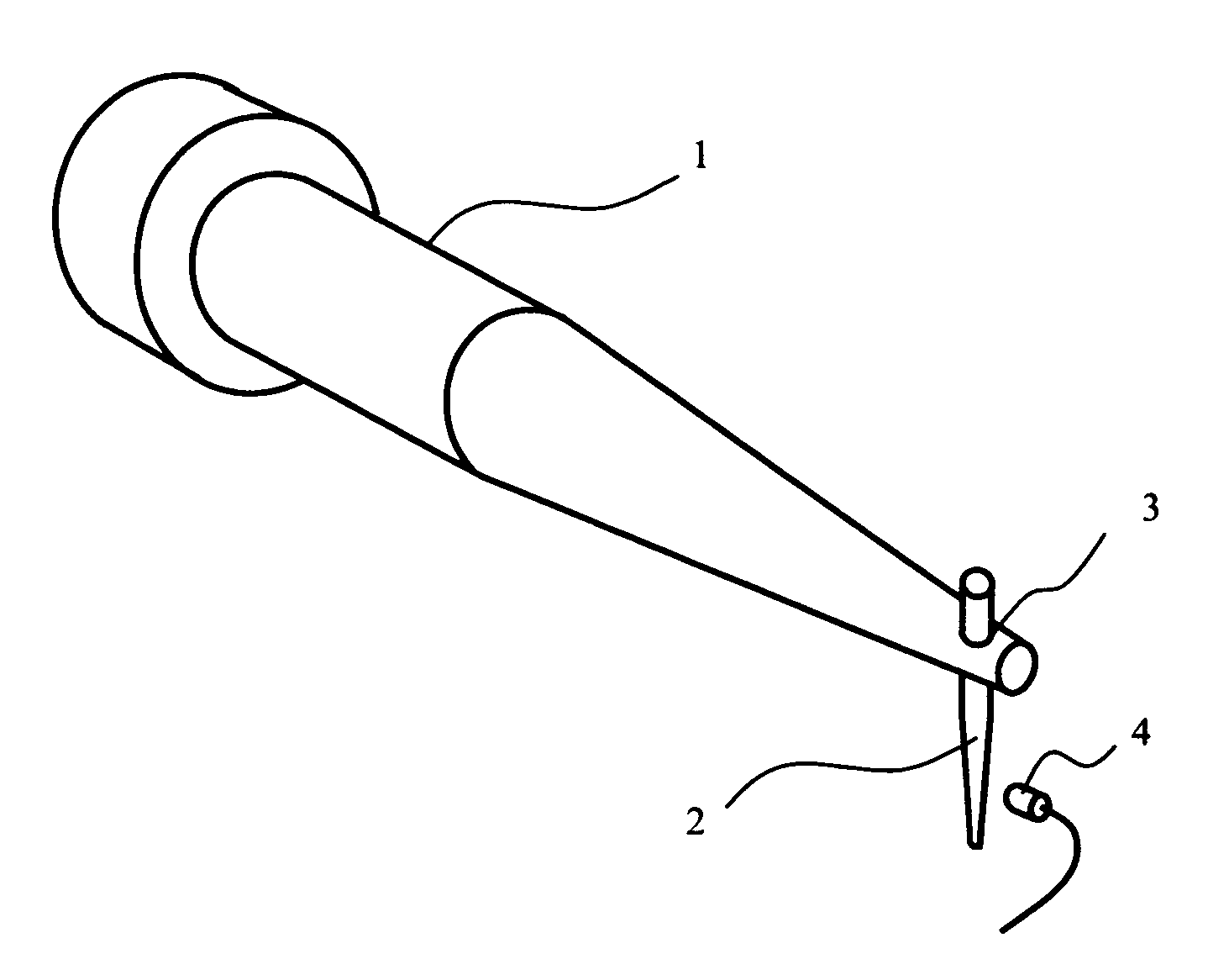
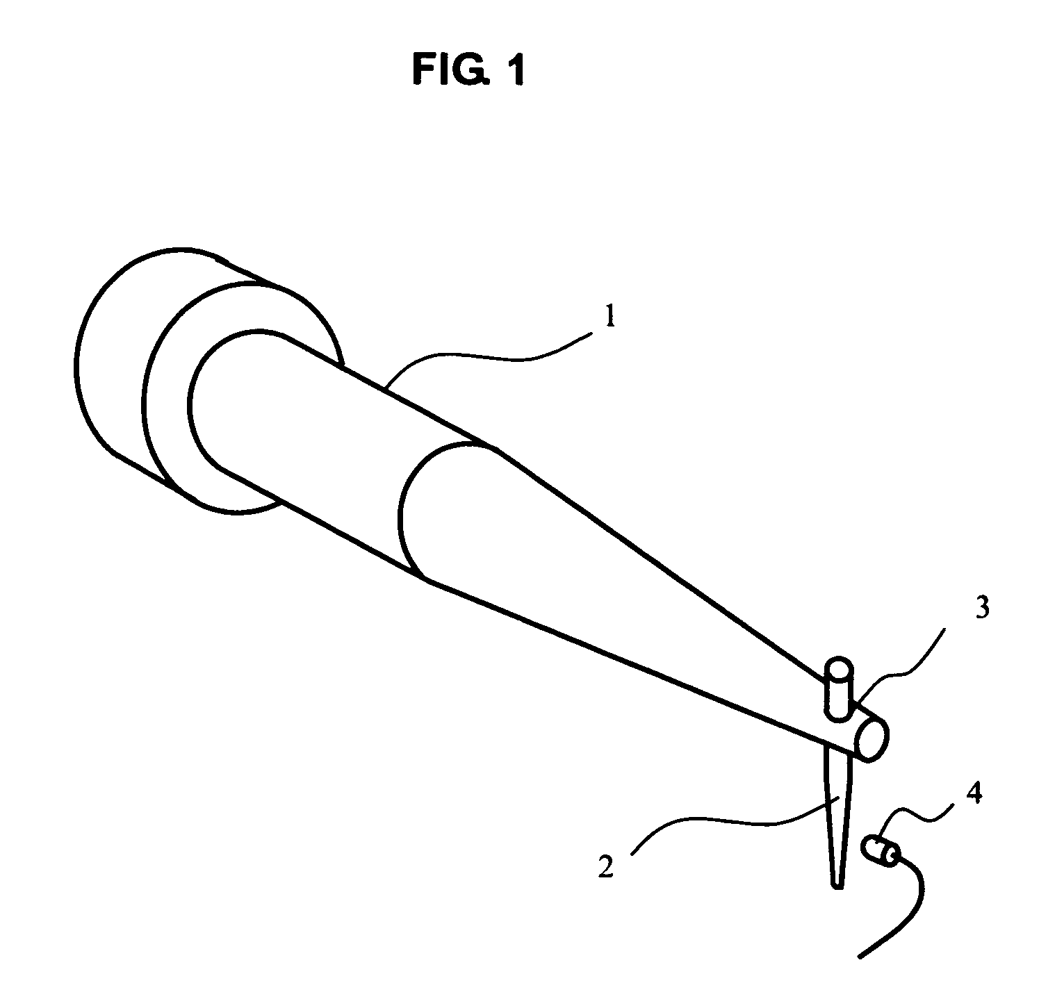
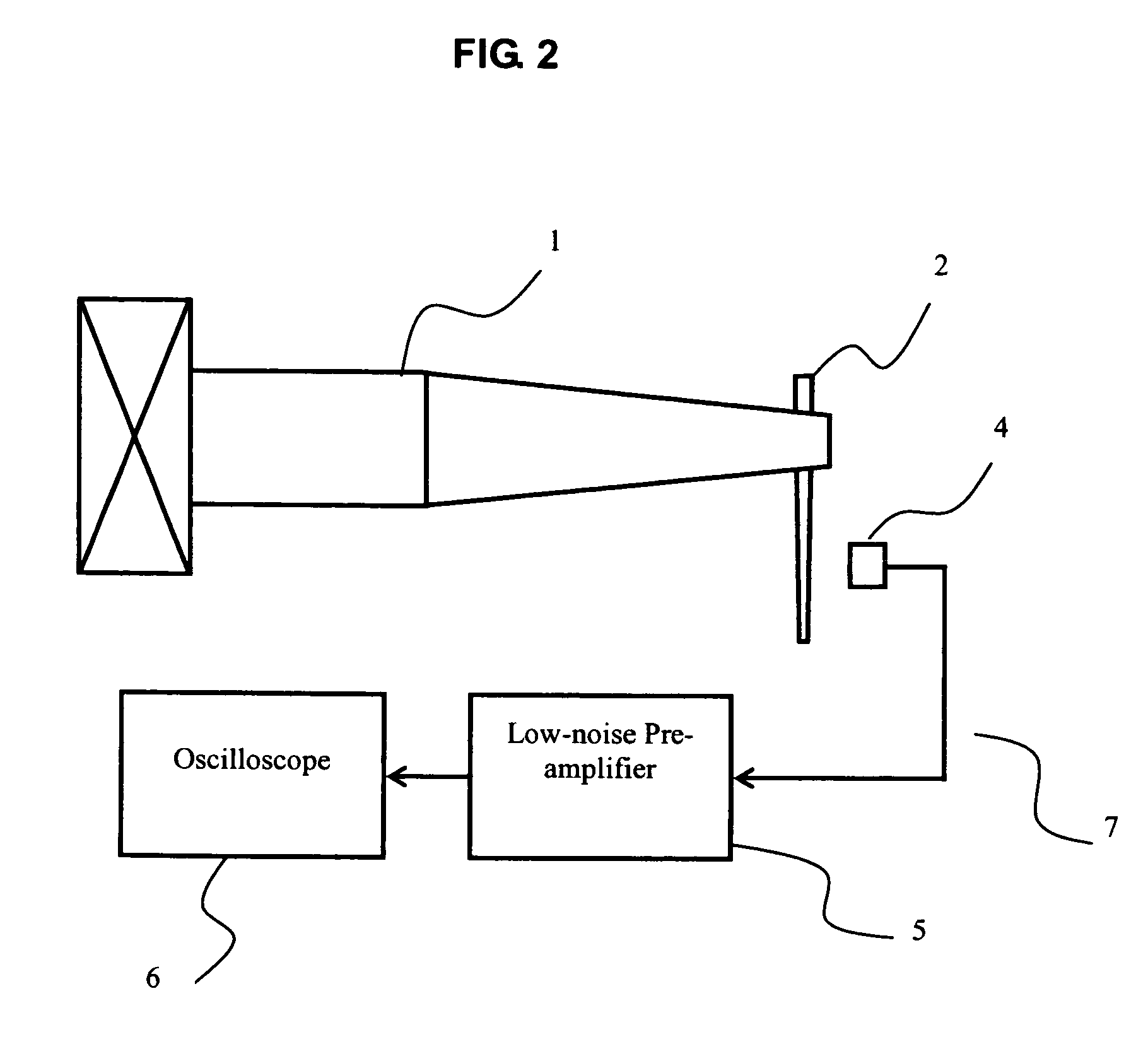
[0017]According to a particular embodiment of the present invention, the piezoelectric sensor is mounted on a printed circuit board with the pair of electrodes being electrically connected to bonding pads on the printed circuit board. A low-noise pre-amplifier, Standford SR570 Low-noise Current Preamplifier, was used for amplifying the signals generated from the sensor, and an oscilloscope is used for observing and processing the signals. The pre-amplifier is optional and the signals can be observed without using the pre-amplifier, albeit not as strong as the one shown with the pre-amplifier. In this instance, a Hewlett-Packard 54645A oscilloscope was used (of which the bandwidth is 100 MHz and sample rate is 200 MSa / s) and, of course, any oscilloscopes with bandwidth and sample rate (for digital storage oscilloscope) large enough to observe the signals without distortion can be satisfactorily used.

Problems solved by technology

Moreover, after the bonding tool has been in service for a period of time, wear and tear will occur and the bonding tool will need to be replaced.
However, these methods either cannot perform real-time measurement or involve complicated operations based on optical methods which are very costly.

Method used


Image

  • Method and apparatus for measuring oscillation amplitude of an ultrasonic device
  • Method and apparatus for measuring oscillation amplitude of an ultrasonic device
  • Method and apparatus for measuring oscillation amplitude of an ultrasonic device

Examples


Embodiment Construction

[0035]Reference will now be made in detail to a preferred embodiment of the invention, examples of which are also provided in the following description. Exemplary embodiments of the invention are described in detail, although it will be apparent to those skilled in the relevant art that some features that are not particularly important to an understanding of the invention may not be shown for the sake of clarity.

[0036]Furthermore, it should be understood that the invention is not limited to the precise embodiments described below and that various changes and modifications thereof may be effected by one skilled in the art without departing from the spirit or scope of the invention. For example, elements and / or features of different illustrative embodiments may be combined with each other and / or substituted for each other within the scope of this disclosure and appended claims.

[0037]In addition, improvements and modifications which may become apparent to persons of ordinary skill in t...


PUM

PropertyMeasurementUnit
resonance frequencyaaaaaaaaaa

Abstract

An apparatus and method for detecting the oscillation amplitude of a bonding tool includes a sensing unit disposed adjacent to and at a distance from the bonding tool. The sensing unit includes a pair of electrodes, a piezoelectric sensing layer located between the pair of electrodes, and a membrane associated with the piezoelectric sensing layer. The piezoelectric sensing layer becomes sensitive to ultrasonic vibrations and generates electrical voltage signals after being activated by a poling process. An optional pre-amplifier is used to amplify the signals generated from the sensing unit, and an oscilloscope is used to further process the signals.

Description

FIELD OF THE INVENTION[0001]The present invention relates to a method and an apparatus for measuring the oscillation amplitude of an ultrasonic tool, particularly a bonding tool of ultrasonic welding device.BACKGROUND OF THE INVENTION[0002]A particular situation related to the present invention is an ultrasonic welding process. During an ultrasonic welding process, for example, in a semiconductor packaging process, conductive wire is bonded between electrical contact pads on the integrated circuit chip (die) and electrical contacts on the leadframe by using an ultrasonic transducer with frequency f (usually 30 kHz≦f≦200 kHz). The ultrasonic transducer has a wedge or capillary bonding tool affixed at the end of the transducer using a screw. It is this tool which applies the ultrasonic vibration from the transducer to the conductive wire to bond the wire onto the die pad or the leadframe. The oscillation amplitude of the bonding tool is one of the critical parameters necessary to achi...

Claims


Application Information

Patent Timeline
Patent Type & Authority Patents(United States)
IPC IPC(8): B23K1/06B23K20/10
CPCH01L24/78H01L2224/78301H01L2224/85205H01L2224/859H01L2924/01029H01L2924/01079H01L2924/14H01L2924/3011H01L2924/01005H01L2924/01006H01L2924/01023H01L2924/01033H01L2224/45147H01L2924/00H01L2924/10253H01L2924/00014H01L2224/48H01L2924/19107H01L2224/45099
Inventor CHAN, HELEN LAI WALAM, TIN YANCHAO, CHENKWOK, KIN WING
Owner THE HONG KONG POLYTECHNIC UNIV
Why Eureka
Try Eureka