Blade for a gas turbine

a gas turbine and blade technology, applied in the direction of machines/engines, liquid fuel engines, mechanical equipment, etc., can solve the problems of increasing the cooling demands of the turbine engine produced today, the likelihood of failure,

Inactive Publication Date: 2010-10-26
SIEMENS ENERGY INC
View PDF51 Cites 44 Cited by
  • Summary
  • Abstract
  • Description
  • Claims
  • Application Information

AI Technical Summary

Problems solved by technology

In addition, turbine vanes and blades often contain cooling systems for prolonging the life of the vanes and blades and reducing the likelihood of failure as a result of excessive temperatures.
While many of these conventional systems have operated successfully, the cooling demands of turbine engines produced today have increased.

Method used


Image

  • Blade for a gas turbine
  • Blade for a gas turbine
  • Blade for a gas turbine

Examples


first embodiment

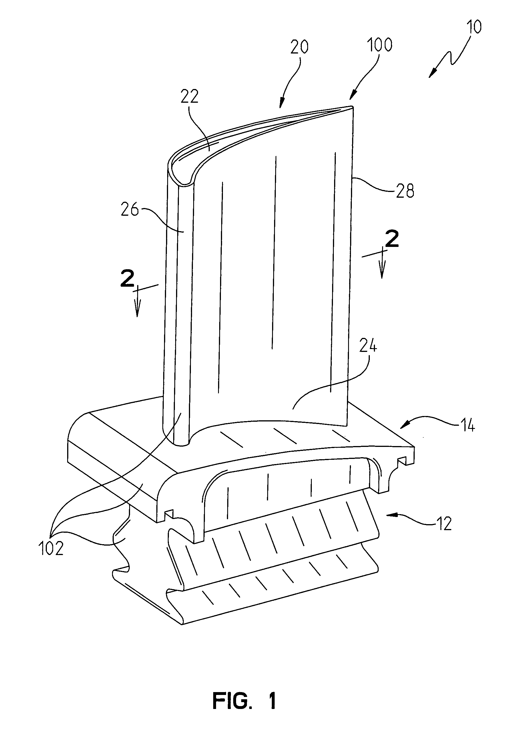
[0035]Referring now to FIG. 1, a blade 10 constructed in accordance with the present invention is illustrated. The blade 10 is adapted to be used in a gas turbine (not shown) of a gas turbine engine (not shown). Within the gas turbine are a series of rows of stationary vanes and rotating blades. Typically, there are four rows of blades in a gas turbine. It is contemplated that the blade 10 illustrated in FIG. 1 may define the blade configuration for a second row of blades in the gas turbine.

[0036]The blades are coupled to a shaft and disc assembly. Hot working gases from a combustor (not shown) in the gas turbine engine travel to the rows of blades. As the working gases expand through the turbine, the working gases cause the blades, and therefore the shaft and disc assembly, to rotate.

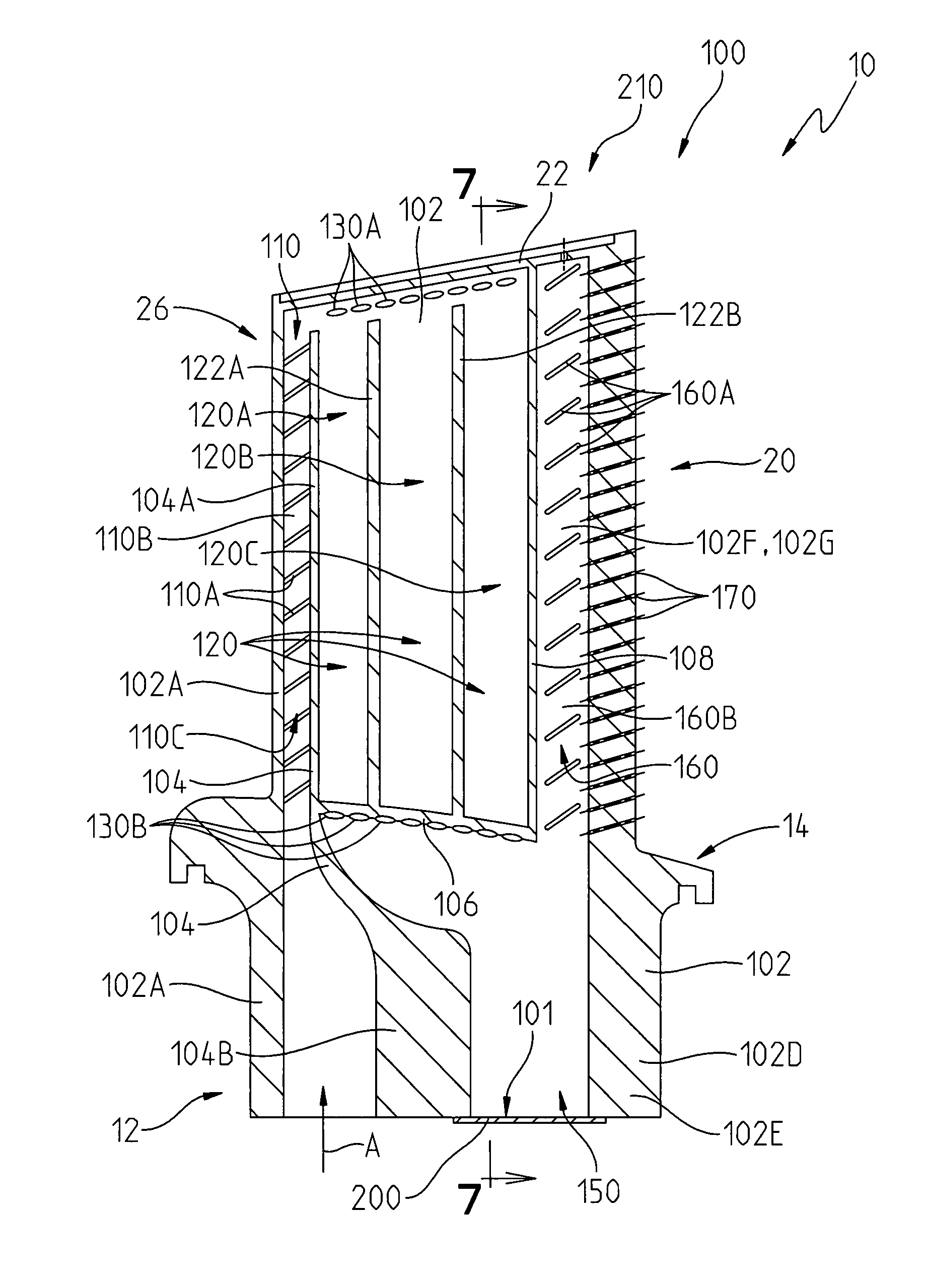
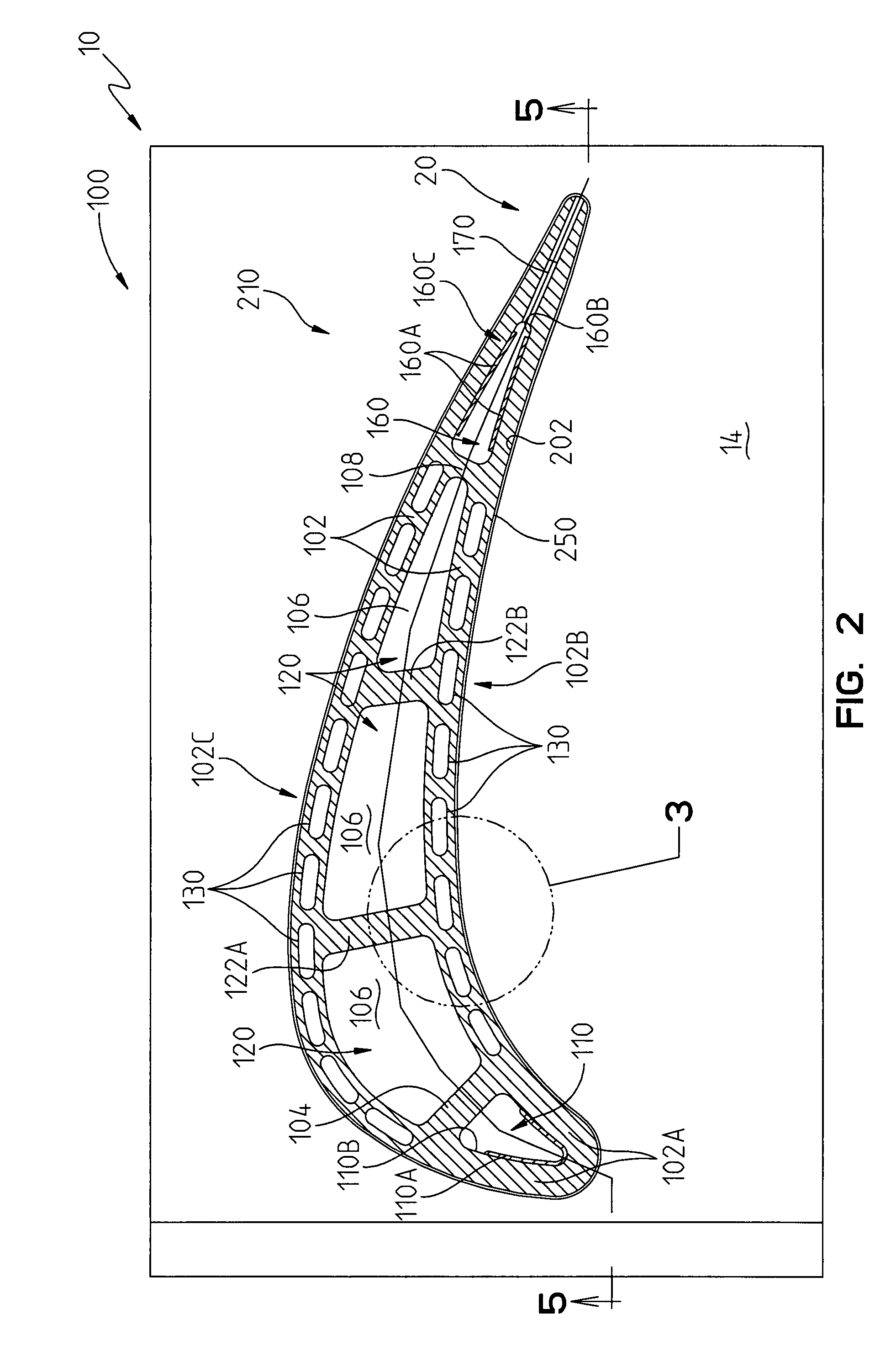
[0037]The blade 10 is defined by a main body 100, which comprises an attachment portion or a root 12, a platform 14 integral with the root 12 and an airfoil 20 formed integral with the platform 14, see...

second embodiment

[0050]In accordance with the present invention, as illustrated in FIGS. 8-10, 10A and 10B, a blade 500, adapted to be used in a gas turbine (not shown) of a gas turbine engine (not shown), is provided. The blade 500 is defined by a main body 600, which comprises a root 512, a platform 514 integral with the root 512 and an airfoil 520 formed integral with the platform 514, see FIGS. 8 and 9. An outer wall 602 of the main body 600 defines portions of the root 512, the platform 514 and the airfoil 520. The airfoil 520 includes a tip 522, a base 524, a leading edge 526 and a trailing edge 528, see FIG. 8. The main body 600, may be formed as a single integral unit from a material such as a metal alloy 247 via a conventional casting operation.

[0051]A conventional thermal barrier coating 750 is provided on an outer surface 702 of the outer wall 602, see FIG. 9.

[0052]Just as in the embodiment illustrated in FIGS. 1-7, the main body 600 comprises a cooling fluid entrance channel 610, a cooli...


PUM


Abstract

A blade is provided for a gas turbine. The blade comprises a main body comprising a cooling fluid entrance channel; a cooling fluid collector in communication with the cooling fluid entrance channel; a plurality of side channels extending through an outer wall of the main body and communicating with the cooling fluid collector and a cooling fluid cavity; a cooling fluid exit channel communicating with the cooling fluid cavity; and a plurality of exit bores extending from the cooling fluid exit channel through the main body outer wall.

Description

[0001]This invention was made with U.S. Government support under Contract Number DE-FC26-05NT42644 awarded by the U.S. Department of Energy. The U.S. Government has certain rights to this invention.FIELD OF THE INVENTION[0002]The present invention relates to a blade for a turbine of a gas turbine engine and, more preferably, to a blade having an improved cooling system.BACKGROUND OF THE INVENTION[0003]A conventional combustible gas turbine engine includes a compressor, a combustor, and a turbine. The compressor compresses ambient air. The combustor combines the compressed air with a fuel and ignites the mixture creating combustion products defining a working gas. The working gas travels to the turbine. Within the turbine are a series of rows of stationary vanes and rotating blades. Each pair of rows of vanes and blades is called a stage. Typically, there are four stages in a turbine. The rotating blades are coupled to a shaft and disc assembly. As the working gas expands through the...

Claims


Application Information

Patent Timeline
Patent Type & Authority Patents(United States)
IPC IPC(8): F01D5/08
CPCF01D5/187F05D2260/2212F05D2260/22141F05D2240/81
Inventor LIANG, GEORGE
Owner SIEMENS ENERGY INC
Why Eureka
Try Eureka