Booting mechanism for FPGA-based embedded system

a technology of embedded systems and boot mechanisms, applied in the field of programable chip systems, can solve the problems of increasing the cost of fpga, slow access to external nonvolatile memory, and using relatively expensive on-chip ram to hold cpu instructions, and achieve the effect of efficient and cost-effective solutions

Active Publication Date: 2010-10-26
TAHOE RES LTD
View PDF14 Cites 50 Cited by
  • Summary
  • Abstract
  • Description
  • Claims
  • Application Information

AI Technical Summary

Benefits of technology

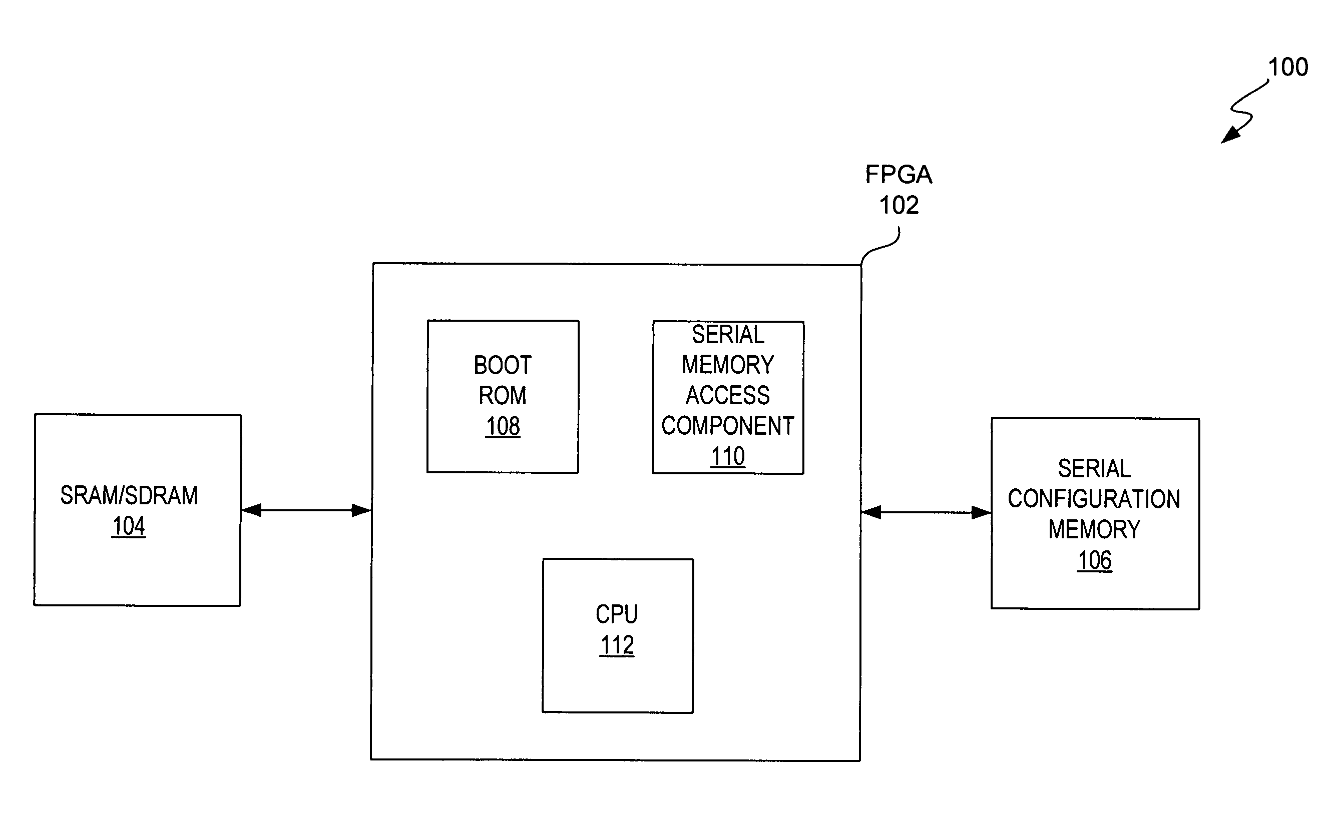
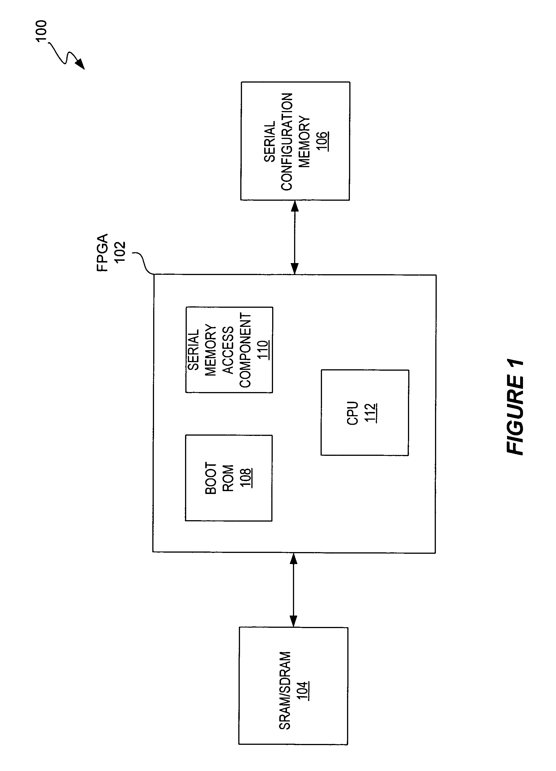
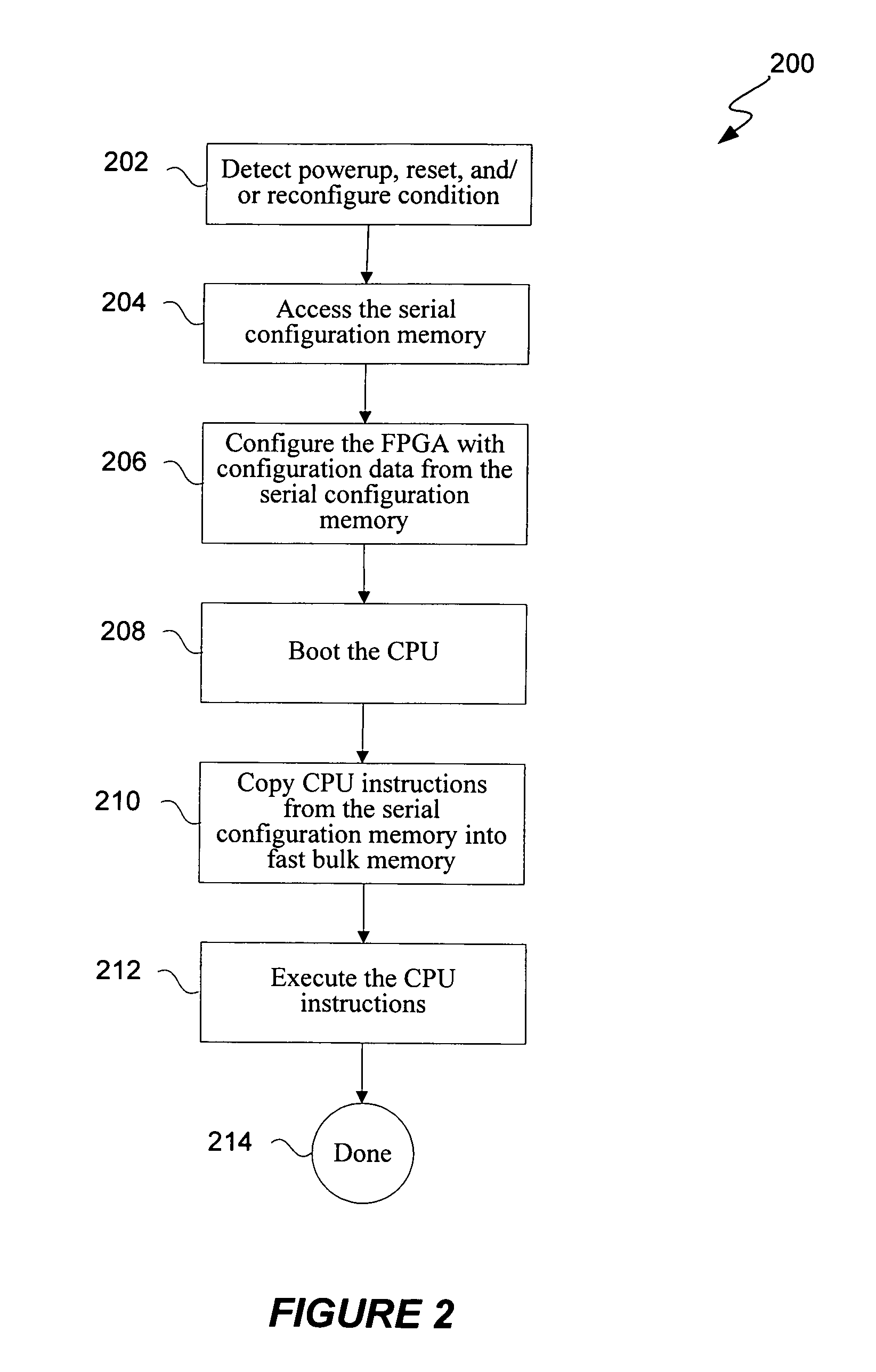
[0012]The techniques and mechanisms of the present invention provide efficient and cost effective solutions for handling a predetermined condition / event (e.g., powerup, reset, and / or reconfigure conditions) associated with a programmable chip system. The predetermined condition / event includes instances where either the CPU must be booted and / or the FPGA must be configured or reconfigured. According to various aspects of the present invention, FPGA configuration data and CPU instructions are stored in at least one nonvolatile serial configuration memory where the FPGA configuration data and / or CPU instructions are accessed upon occurrence of the predetermined condition.

Problems solved by technology

The disadvantage of this approach is that it uses relatively expensive on-chip RAM to hold the CPU instructions.
This approach has the advantage that no on-chip RAM is needed for boot memory, but it has the disadvantage that accessing external nonvolatile memory is slow.
These kinds of memory are much less expensive than on-chip RAM and faster than off-chip nonvolatile memory, but they have many address and data pins which must be connected to corresponding FPGA pins, thereby adding to the FPGA cost.
The disadvantage of this approach is that it uses an additional external logic device.

Method used


Image

  • Booting mechanism for FPGA-based embedded system
  • Booting mechanism for FPGA-based embedded system
  • Booting mechanism for FPGA-based embedded system

Examples


Embodiment Construction

[0024]Reference will now be made in detail to some specific embodiments of the invention including the best modes contemplated by the inventors for carrying out the invention. Examples of these specific embodiments are illustrated in the accompanying drawings. While the invention is described in conjunction with these specific embodiments, it will be understood that it is not intended to limit the invention to the described embodiments. On the contrary, it is intended to cover alternatives, modifications, and equivalents as may be included within the spirit and scope of the invention as defined by the appended claims.

[0025]For instance, the techniques of the present invention will be described in the context of particular design automation tools. However, it should be noted that the techniques of the present invention can be applied to a variety of tools and associated code provided with the tools. In the following description, numerous specific details are set forth in order to pro...


PUM


Abstract

According to various embodiments of the present invention, a programmable device assembly includes an FPGA coupled to a nonvolatile serial configuration memory (e.g., serial flash memory) and a volatile fast bulk memory (e.g., SRAM or SDRAM). The nonvolatile serial configuration memory contains both the FPGA configuration data and CPU instructions. When a predetermined condition occurs, a serial memory access component that is hard coded on the FPGA automatically reads the configuration data from the nonvolatile serial configuration memory. The configuration data is used to configure the FPGA with various components, including a CPU, a boot ROM with code for a boot copier, and a bus structure. When the CPU boots, code for the boot copier is executed so that the CPU instructions are copied from the nonvolatile serial configuration memory to the volatile fast bulk memory. The CPU then executes the CPU instructions stored in the volatile fast bulk memory.

Description

BACKGROUND[0001]1. Field of the Invention[0002]The present invention generally relates to programmable chip systems. More specifically, the invention relates to mechanisms and techniques for booting FPGA-based embedded systems.[0003]2. Description of Related Art[0004]The central processing unit (CPU) of an embedded system must start up or “boot” when it first receives power and then again whenever it receives a reset pulse. Usually, the instructions that the processor executes are stored in nonvolatile memory (e.g., EPROM, EEPROM, or ROM) or in a nonvolatile memory on the micro-controller device.[0005]In embedded systems that contain a field programmable gate array (FPGA), the FPGA must configure itself when it first receives power and then again whenever it receives a reconfigure pulse. Usually, the configuration data for an FPGA is also stored in a separate nonvolatile memory.[0006]Although storing the CPU instructions and the FPGA configuration data on separate nonvolatile memori...

Claims


Application Information

Patent Timeline
Patent Type & Authority Patents(United States)
IPC IPC(8): G06F9/00G06F9/24G06F13/00
CPCG06F9/4401
Inventor ALLEN, TIMOTHY P.DRAPER, ANDREWFERRUCCI, AARONVEENSTRA, KERRY
Owner TAHOE RES LTD
Why Eureka
Try Eureka