Closed-loop downhole resonant source

a closed loop, resonant source technology, applied in the direction of instruments, survey, borehole/well accessories, etc., can solve the problems of affecting the outcome, difficult system implementation, and inability to maintain identical recording conditions for an extended time period, and achieve the effect of expanding the operating capability of the borehole sour

Active Publication Date: 2010-11-02
BAKER HUGHES INC
View PDF78 Cites 25 Cited by
  • Summary
  • Abstract
  • Description
  • Claims
  • Application Information

AI Technical Summary

Benefits of technology

[0029]The control unit controls the operation of the drive source. In one embodiment, the control unit is linked to the drive source and can issue command signals for adjusting one or more parameters of interest. In one embodiment, the control unit also includes one or more sensor for measuring operating and/or performance parameters of interest. Exemplary parameters of interest include pressure and temperature in the cavity, rotational speed of a rotary valve, fluid flow rate, and pressure waves generated by the cavity. In certain embodiments, the control unit can be replaced with simplified mechanical, electromechanical, or hydraulic linkages and other suitable devices in lieu of electronic circuitry and computer control. In one exemplary mode of operation, the control unit collects and transmits sensor data to the surface and executes commands transmitted from the surface. The control unit can include one or more processors to process or condition the signal prior to transmission. In another mode of operation, the control unit controls the operation of the borehole source in a closed-loop fashion according to pre-programmed instructions in a memory module. The control and data signals can be transmitted by a suitable two-way telemetry system.
[0030]In another aspect, the present invention provides a borehole source that utilizes a smart fluid in a closed-loop fluid system as a resonant fluid. A “smart” or “controllable” fluid are materials that respond to an applied excitation field such as an electric or magnetic field with a change in their Theological behavior. In this embodiment, the borehole source includes a resonant cavity for generating resonant energy, a closed loop drive source and a control unit. In one embodiment, the closed-loop drive source includes a fluid reservoir, a pump, an accumulator, an excitation valve and a bleed line. The use of a smart fluid for the circulating fluid extends the operating capability of the borehole source and adds additional measures of control and functionality to the borehole source. In one embodiment, the cavity includes an excitation c

Problems solved by technology

This criterion is severe because changes in the data-acquisition equipment and changes in the processing algorithms, inevitable over many years may introduce differences among the separate, individual data sets from surveys that are due to instrumentation, not the result of dynamic reservoir changes.
In particular, using conventional surface exploration techniques, long-term environmental changes in field conditions such as weather and culture may affect the outcome.
The requirement for an active source to be placed at various levels in the borehole is problematic because the source can damage the hole and interfere with production.
Since the seismic equipment must be moved up and down the boreholes, it is impossible to maintain identical recording conditions over an extended time period.
That system thus is difficult to implement for the fixed permanent instrumental installation required for 4-D seismic monitoring operation.
A further disadvantage of this scheme is that very high energy tube waves are required, which in turn leads t

Method used


Image

  • Closed-loop downhole resonant source
  • Closed-loop downhole resonant source
  • Closed-loop downhole resonant source

Examples


Embodiment Construction

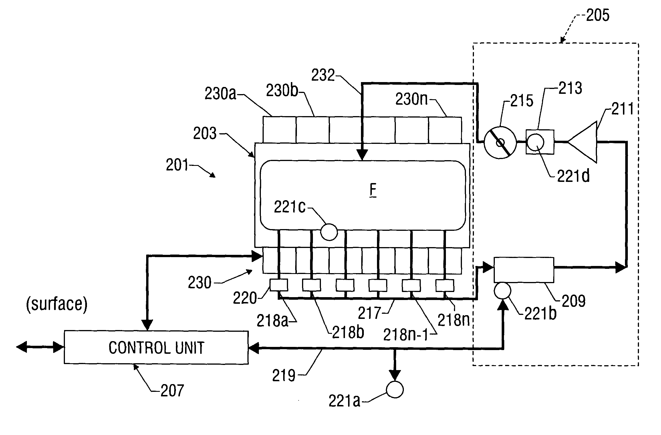
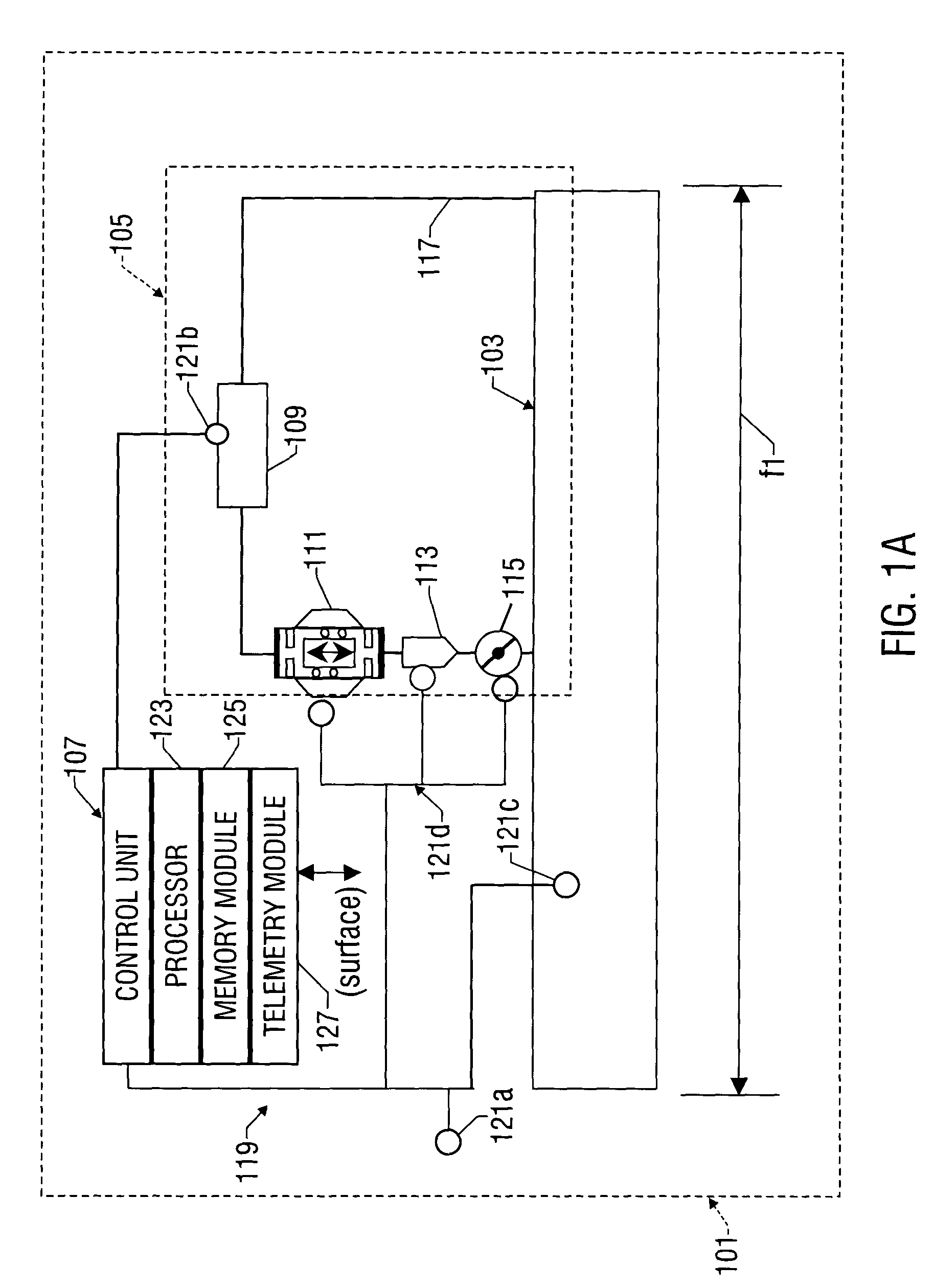
[0043]The present invention is a method and system for creating and measuring a seismic wavefield for monitoring the distribution of the contents of a subsurface mineral deposit over its economic life span for long-term resource management. The system employs pressure waves generated within well bore structures. The wellbore structure contains a resonant cavity outside of at least one wellbore tubular. The resonant cavity receives pressure energy from a drive source and thereby develop seismic waves in a resonant cavity that is designed to impart these waves into a surrounding formation. The pressure waves in the resonant cavity are coupled to the wellbore structure and are converted to seismic body waves in the adjacent earth formation and radiate away from the well. These seismic body waves detected by sensors may be processed to indicate parameters of interest in the subsurface earth formation.

[0044]Time varying changes of selected attributes of those seismic waves that have tran...


PUM


Abstract

An apparatus for generating seismic body waves in a hydrocarbon reservoir includes a closed-loop borehole source having a resonant cavity for generating resonant energy, a drive source and a control unit. The drive source injects pressure pulses to the resonant cavity at a predetermined or selectable pressure and frequency. The fluid circulates between the cavity and the drive source in a closed-loop fashion. In another embodiment, the borehole source utilizes a smart or controllable material that is responsive to an applied excitation field. The cavity includes an excitation coil for providing an excitation field that changes a material property of the smart fluid. The control unit is programmed to adjust operating parameters to produce seismic waves having a selected frequency and amplitude. In one embodiment, a control unit adjusts operating parameters in response to measured parameters of interest or surface commands.

Description

CROSS-REFERENCE TO RELATED APPLICATIONS[0001]This application is a continuation-in-part of U.S. patent application Ser. No. 10 / 366,841, filed on Feb. 14, 2003 now U.S. Pat. No. 6,795,373. This application is also a continuation-in-part of U.S. patent application Ser. No. 10 / 444,857 filed on May 23, 2003 now U.S. Pat. No. 6,926,089, which is a continuation of U.S. application Ser. No. 09 / 916,617 filed on Jul. 27, 2001, now U.S. Pat. No. 6,568,470.FIELD OF THE INVENTION[0002]The invention relates to the downhole generation of seismic waves for use in investigation and monitoring of earth formation reservoir characteristics surrounding a well borehole. In one aspect, the invention relates to a method and system for producing seismic energy using a seismic source using a closed fluid loop. In another aspect, the invention relates to a closed-loop seismic source employing materials responsive to an excitation signal. The present invention also relates to using seismic body waves radiated...

Claims


Application Information

Patent Timeline
IPC IPC(8): G01V1/40E21B23/04E21B33/1295E21B34/00F15B21/06G01V1/133G01V1/42
CPCG01V1/133G01V1/42
Inventor ARONSTAM, PETER S.WATKINS, LARRYFINCHER, ROGERGOODSON, JR., JAMES E.CARMODY, MICHAEL
Owner BAKER HUGHES INC
Why Eureka
Try Eureka