Drive of an electromagnetic valve with a coil by supplying high voltage from a discharging capacitor to the coil

a technology of electromagnetic valve and coil, which is applied in the direction of electric control, pulse technique, machines/engines, etc., can solve the problems of deteriorating the responsiveness of the electromagnetic valve to the valve opening, adverse effect on the reception conditions, and inapplicability

Inactive Publication Date: 2010-11-02
DENSO CORP
View PDF23 Cites 11 Cited by
  • Summary
  • Abstract
  • Description
  • Claims
  • Application Information

AI Technical Summary

Benefits of technology

[0032]The present invention has been made in light of the problem mentioned above and has as its object to provide an electromagnetic valve driving apparatus that can reduce emission noise, which is produced when a discharge switching element is in an off-state.
[0035]Further, the discharge switching element is provided in series in the current path extending from the discharging capacitor to the upstream-side terminal of the coil of the electromagnetic valve. The discharge switching element is turned on by the controlling means when the driving period for supplying current to the coil of the electromagnetic valve is started to establish an electrical connection to the discharging capacitor. As a result, current is discharged from the discharging capacitor to the coil, so that the electromagnetic valve can be promptly brought into an operating state.
[0038]The electromagnetic valve driving apparatus of the present invention does not immediately stop discharging to the coil when the discharge switch is switched from an on-state to an off-state, but continues discharging to the coil with the aid of the sub-discharging means and, when the discharging of the sub-discharging means is finished, circulates current to the coil through the circulating means. Therefore, voltage variation (corresponding to the voltage variation at the output terminal P1 shown in FIGS. 12 and 13) at the upstream-side terminal of the coil can be mitigated when the discharge switch is switched from an on-state to an off-state.

Problems solved by technology

As a result, emission noise of an amount corresponding to the voltage variation may be caused to adversely effect reception conditions, for example, of radios.
The former approach however may deteriorate valve-opening responsiveness of the electromagnetic valve 21.
The latter approach is also not practical because it may increase power loss of the switch 11, which may also increase the heat generation rate.

Method used


Image

  • Drive of an electromagnetic valve with a coil by supplying high voltage from a discharging capacitor to the coil
  • Drive of an electromagnetic valve with a coil by supplying high voltage from a discharging capacitor to the coil
  • Drive of an electromagnetic valve with a coil by supplying high voltage from a discharging capacitor to the coil

Examples


first embodiment

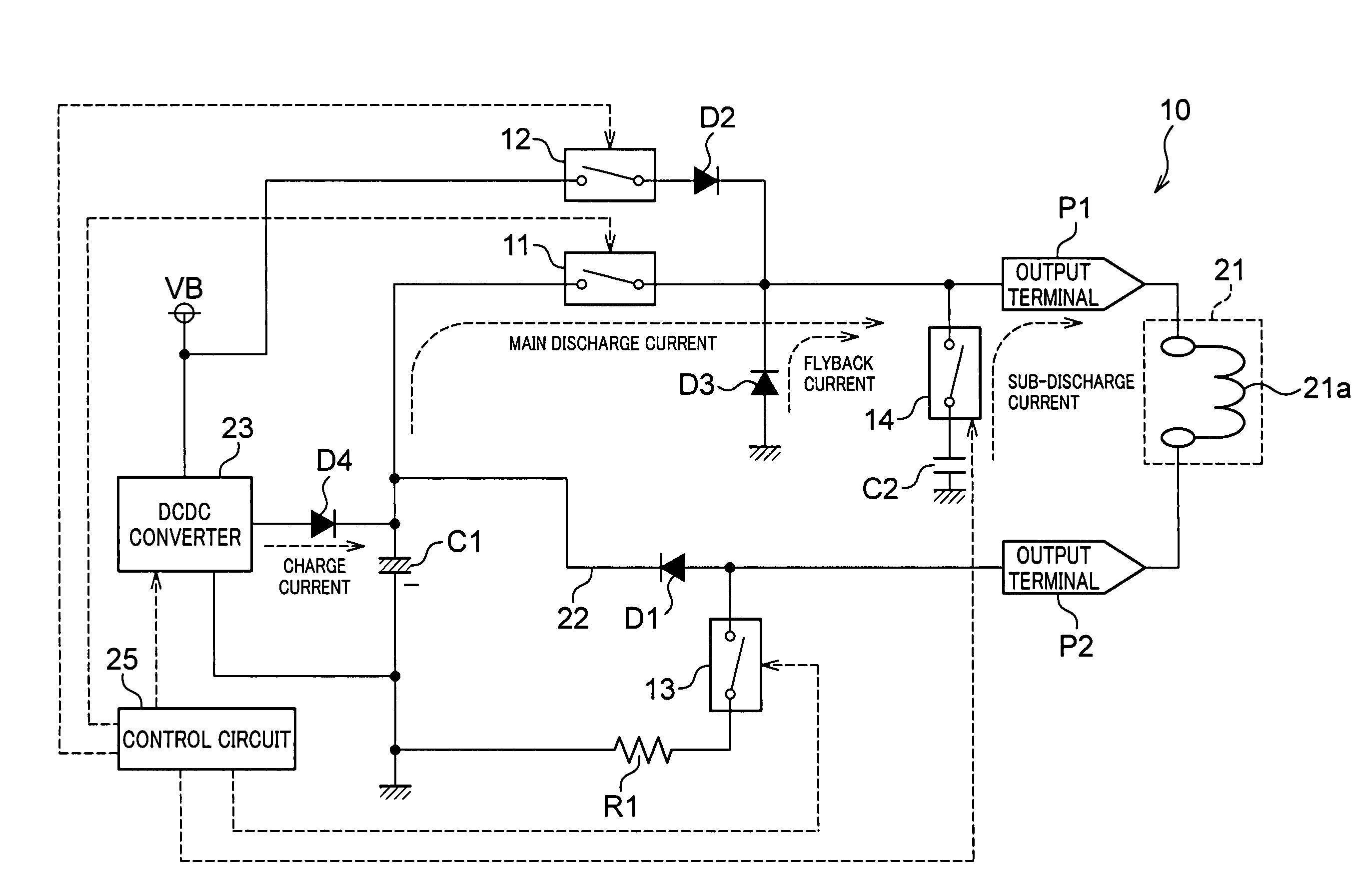
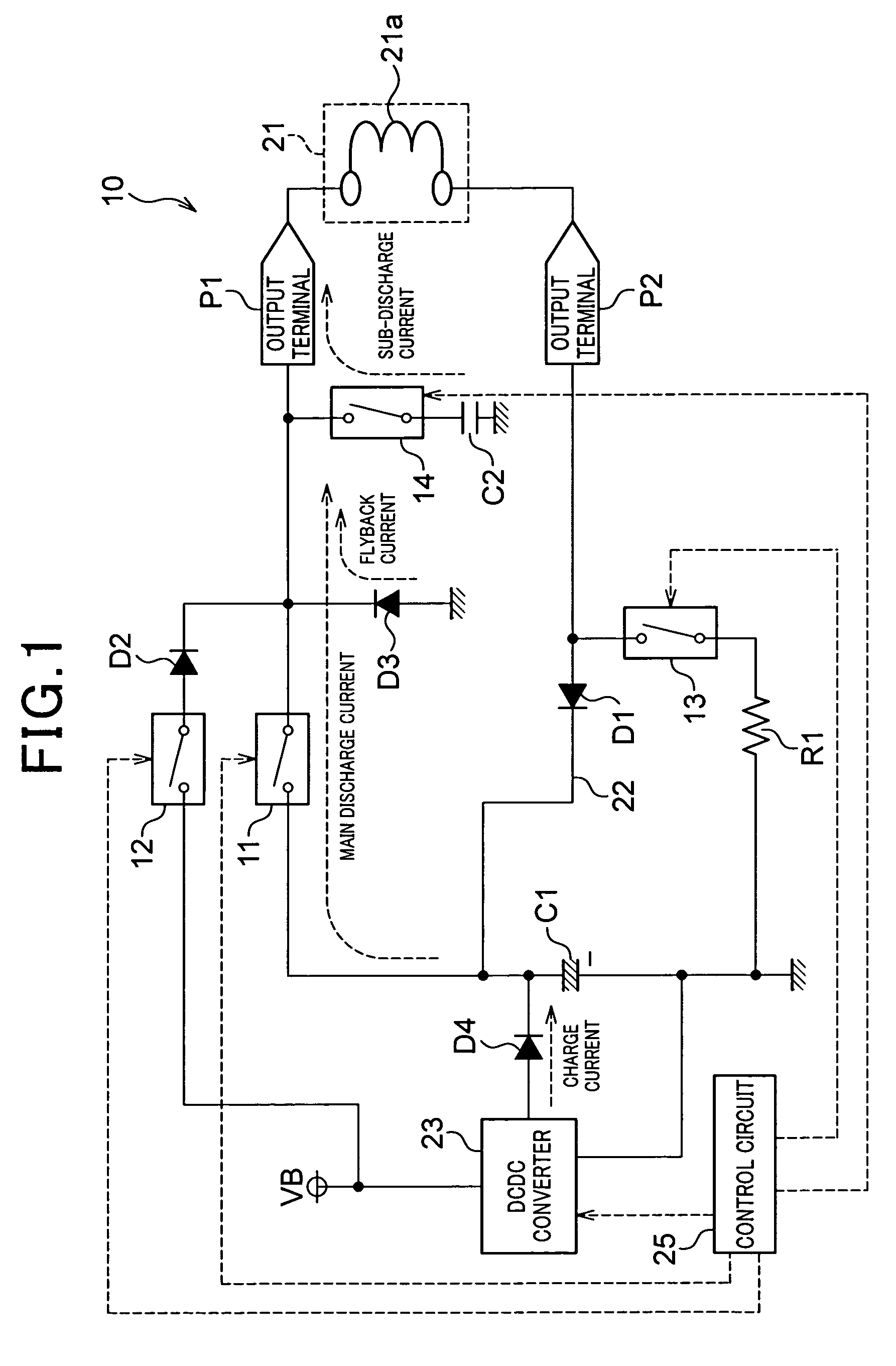
[0055]As shown in FIG. 1, a fuel injection control apparatus 10 according to a first embodiment is different from the fuel injection control apparatus 100 shown in FIG. 12 in the points as provided at the following items (1-1) and (1-2).

[0056](1-1) A series circuit consisting of a capacitor C2 and a switch 14 is additionally provided in parallel with the diode D3 in order to perform the sub-discharge subsequent to the main discharge. The capacitor C2 is adapted to establish an electrical connection between the output terminal P1 (or wiring connecting between the switch 11 and the output terminal P1) and the ground line when the switch 14 is turned on. The switch 14 is also controlled by the control circuit 25.

[0057]The capacitor C1 is an aluminium electrolytic capacitor or a film capacitor, while the capacitor C2 is of the type having smaller equivalent series inductance (ESL) and higher discharging speed than the capacitor C1 (stacked ceramic capacitor in the present embodiment).

[0...

second embodiment

[0085]As shown in FIG. 7, a fuel injection control apparatus 30 according to a second embodiment is different from the fuel injection control apparatus 10 according to the first embodiment in the points provided at the following items (2-1) and (2-2).

[0086]It should be appreciated that, in the second and the subsequent embodiments, the identical or similar components to those in the first embodiment are given the same reference numerals for the sake of simplifying or omitting the explanation.

[0087](2-1) A DCDC converter 29 similar to the DCDC converter 23 is additionally provided. The DCDC converter 29 generates voltage higher than the battery voltage VB, and this high voltage is provided to the capacitor C2 through a diode D5 so that the capacitor C2 can be charged. The DCDC converter 29 is controlled by the control circuit 25.

[0088](2-2) As shown in FIG. 8, when executing sub-discharge, the control circuit 25 operates the DCDC converter 29 while turning off the switches 11 and 14,...

third embodiment

[0094]As shown in FIG. 9, a fuel injection control apparatus 40 according to a third embodiment is different from the fuel injection control apparatus 10 according to the first embodiment in the points as provided at the following items (3-1) and (3-2).

[0095](3-1) A resistor R2 is connected in series with the capacitor C2, for detecting current discharged to the coil 21a from the capacitor C2.

[0096](3-2) The voltage across the resistor R2 is amplified by an amplifier 25a in the control circuit 25.

[0097]In performing sub-discharge, the control circuit 25 monitors the output of the amplifier 25a every time the switch 11 is changed from an on-state to an off-state, so as to determine whether or not current is discharged from the capacitor C2 to the coil 21a. At the same time, the control circuit 25 measures duration of a period, which has been determined as being used for performing discharge, as a period of discharge from the capacitor C2 to the coil 21a. Further, upon determining the...


PUM


Abstract

An electromagnetic valve driving apparatus is provided for reducing emission noise generated when a discharge switching element is turned off. In the apparatus, a discharging capacitor stores electrical energy for performing discharge to a coil in an electromagnetic valve and charging means generates voltage from a power source voltage, which voltage is higher than that of the power source voltage. A discharge switching element is provided in series in a current path extending from the discharging capacitor to an up-stream side terminal of the coil. Controlling means turns on / off the discharge switching element. Circulating means is provided in the current path for circulation of current to the coil. Sub-discharging means is provided in the current path, for starting discharge to the coil when the discharge switching element is turned off, and for circulating current to the coil through the circulating means when the discharge to the coil is completed.

Description

CROSS-REFERENCE TO RELATED APPLICATION[0001]This application is based on and claims the benefit of priority from earlier Japanese Patent Application No. 2006-254658 filed Sep. 20, 2006, the description of which is incorporated herein by reference.BACKGROUND OF THE INVENTION[0002]1. Technical Field of the Invention[0003]The present invention relates to an apparatus for driving electromagnetic valves, and in particular, to the apparatus adapted to discharge high-voltage energy charged to a discharging capacitor, into a coil in an electromagnetic valve to enhance the operational responsiveness of the electromagnetic valve.[0004]2. Related Art[0005]Fuel injection valves are used, for example, for injecting and supplying fuel to individual cylinders of an internal combustion engine loaded on a vehicle. Electromagnetic valves have been used as fuel injection valves, which are opened by supplying current to coils. Such fuel injection valves are driven and controlled by a fuel injection con...

Claims


Application Information

Patent Timeline
Patent Type & Authority Patents(United States)
IPC IPC(8): F02D41/20
CPCF02D41/20H03K17/16H03K17/687F02D2041/2006
Inventor UEDA, KOUJI
Owner DENSO CORP
Why Eureka
Try Eureka