14 mm extension spark plug

a spark plug and extension technology, applied in the field of extension spark plugs, can solve the problems of reducing the maximum operating temperature of the extension spark plug, reducing the electrical isolation capacity of the material, and not necessarily providing desirable electrical isolation characteristics

Active Publication Date: 2010-11-02
FEDERAL MOGUL IGNITION
View PDF33 Cites 17 Cited by
  • Summary
  • Abstract
  • Description
  • Claims
  • Application Information

AI Technical Summary

Problems solved by technology

Skilled laborers must be employed to perform the required assembly due to the complexity of the operation.
For example, attachment of the shell extension to the shell may use press-fit connections which are prone to coming apart in the field.
Field assembly necessitates that any metallurgical bond used to attach the shell extension to the shell utilize relatively low temperature processes, such as soldering or low-temperature brazing which produce relatively weak mechanical joints which can later result in failure while installing or uninstalling the spark plug.
So further, extension kits frequently utilize combinations of elastomeric and plastic insulating materials, as they are more durable with respect to field assembly and installation; however such materials do not necessarily provide desirable electrical isolation characteristics.
Because field installed extensions are typically non-hermetic, moisture and other contaminants are accessible to the insulating materials, thereby diminishing their electrical isolation capabilities.
Such materials also limit the maximum operating temperature of the extension spark plug based on inherent characteristics of materials such as a softening point or a glass transition point of the plastic materials used.
Those that are known typically employ many of the same components and manufacturing methods described above, and thus are generally subject to the same limitations.

Method used


Image

  • 14 mm extension spark plug
  • 14 mm extension spark plug
  • 14 mm extension spark plug

Examples


Embodiment Construction

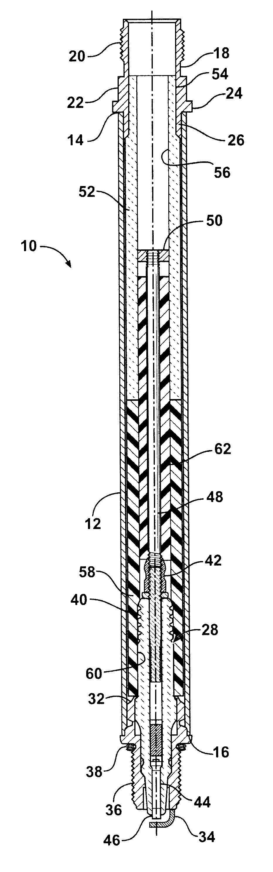
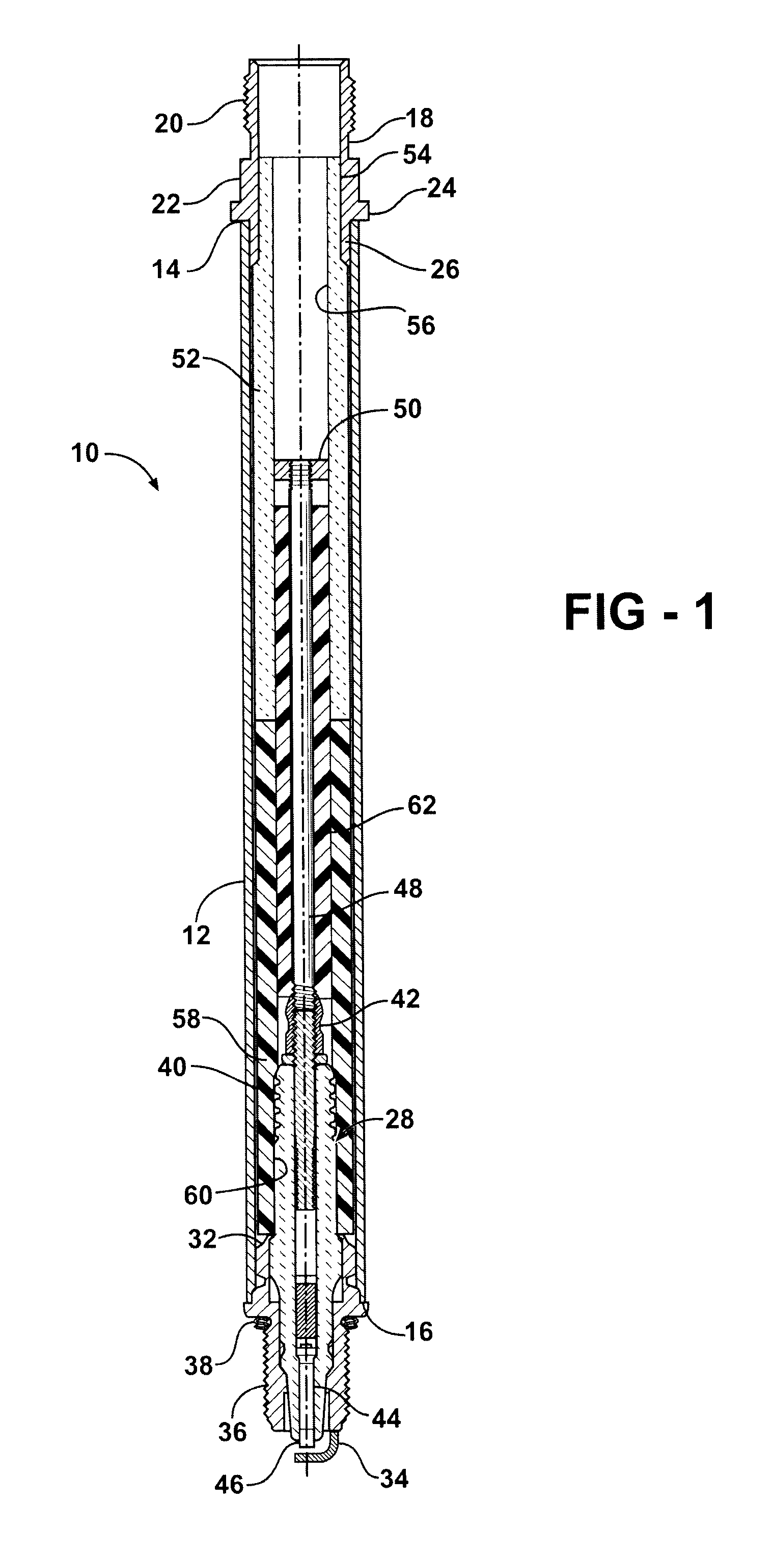
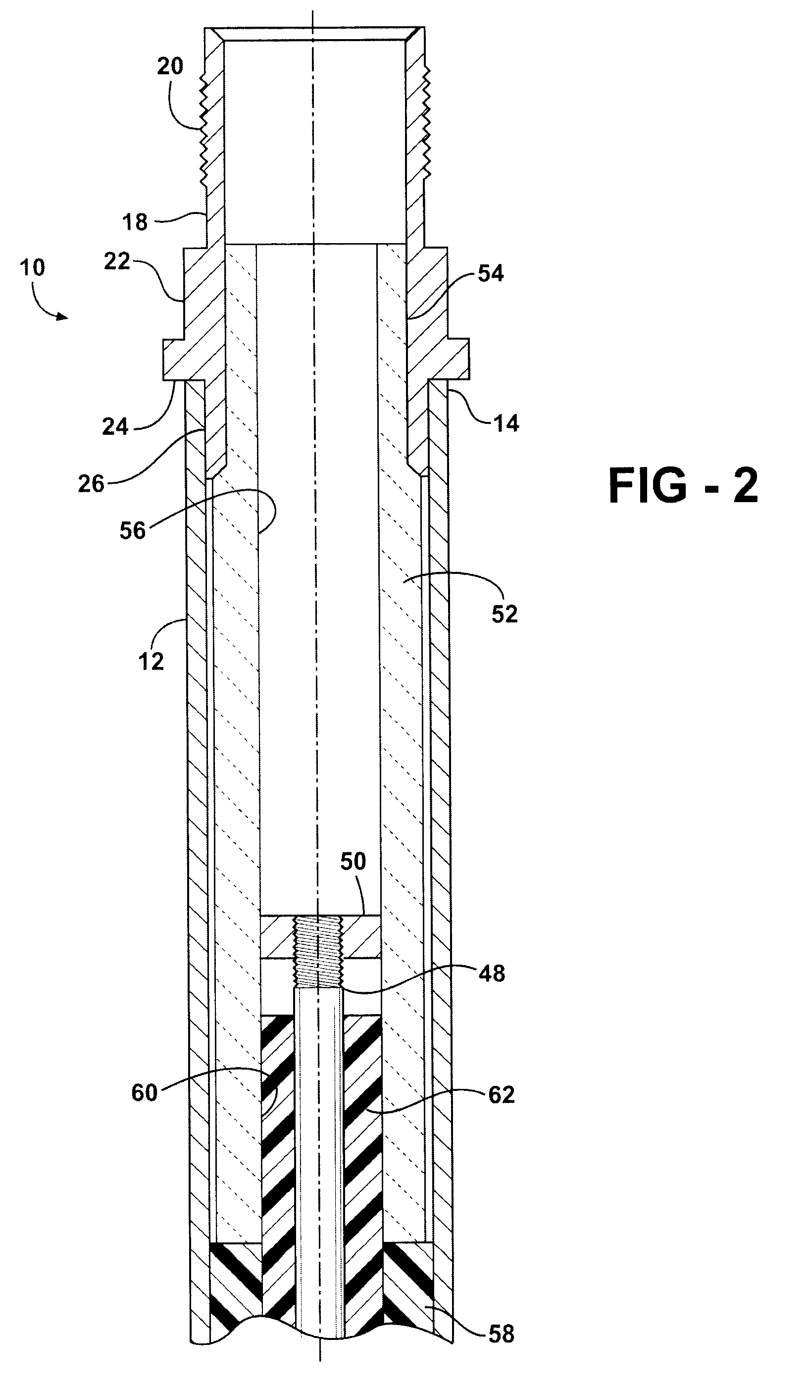
[0018]Referring to FIGS. 1-6, wherein like numerals indicate like or corresponding parts throughout the several views, an extension-type spark plug in accordance with an embodiment of the present invention is generally shown at 10. The extension spark plug 10 is of the type and size, such as M14 as but one example, used in industrial engines and other specialized applications where access to the spark plug 10 for maintenance and replacement purposes is severely limited. The spark plug assembly 10 includes a conduit sheath extension tube 12 preferably made from a corrosion and oxidation resistant metal material, such as stainless steel or an alloy thereof. The conduit 12 is substantially cylindrical along its length and has a generally thin wall section extending between top end 14 and bottom end 16. In an exemplary embodiment, conduit 12 has a length of 8-12 inches, an outside diameter of 0.8-1.0 inches and a wall thickness of about 0.06 inches.

[0019]A bushing 18 is fitted into the ...


PUM


Abstract

A spark plug assembly (10) for engine applications where the combustion chamber is difficult to access when servicing or replacing a spark plug. The spark plug assembly (10) includes a fairly traditional spark plug component (28) to which an elongated tubular conduit (12) is attached, such as by welding, to a portion of the metallic shell (32). The conduit (12) contains an upper ceramic insulator (52) adjacent its top end (14) disposed in end-to-end abutting contact with an outer elastomeric insulator (58). The ceramic insulator of the spark plug component (28), herein referred to as a lower ceramic insulator (30), is surrounded by the outer elastomeric insulator (58) and held securely within the conduit (12) thereby. An inner elastomeric insulator (62) is disposed in a continuous passageway formed between aligned central bores formed in the respective upper ceramic (52) and outer elastomeric (58) insulators. The inner elastomeric insulator (62) supports and further electrically isolates an elongated electrically conductive center electrode extension (48) that is in direct electrical conductivity with the center electrode (44) of the spark plug component (28). An ignition lead wire makes electrical contact with the center electrode extension (48) and thereby delivers electrical energy at timed intervals to the spark gap.

Description

CROSS REFERENCE TO RELATED APPLICATIONS[0001]This patent application claims priority to U.S. Provisional Patent Application Ser. No. 60 / 893,392, filed Mar. 7, 2007, which is incorporated herein by reference in its entirety.BACKGROUND OF THE INVENTION[0002]1. Field of the Invention[0003]The subject invention relates to spark plugs for igniting combustion gases in a combustion chamber of an internal combustion engine, and more particularly toward an extension type spark plug as used chiefly in stationary engine applications such as generators, pumps and the like.[0004]2. Related Art[0005]Extension type spark plugs are used in applications where the depth of the spark plug bore in the cylinder head requires the use of an unusually long spark plug. While specialty spark plugs can be designed for these applications, it is sometimes preferred to adapt extensions for conventional, long-life spark plugs for these purposes.[0006]One approach to providing the necessary extensions has been to ...

Claims


Application Information

Patent Timeline
Patent Type & Authority Patents(United States)
IPC IPC(8): H01T13/00
CPCH01T13/06H01T13/08H01T13/20
Inventor CALLAHAN, RICHARD E.FREEMAN, ROBERT D.
Owner FEDERAL MOGUL IGNITION
Why Eureka
Try Eureka