Haze reduction method and apparatus for use in retinal imaging

a retinal image and haze reduction technology, applied in the field of retinal imaging, can solve the problems of reducing the current draw, unable to solve the current draw problem by reducing the data rate or frequency, and unable to reduce the current draw, so as to reduce the overall average current draw, eliminate haze, and reduce the driver current in digital retinal image transfer

Inactive Publication Date: 2010-11-09
SONOMED IP HLDG
View PDF9 Cites 0 Cited by
  • Summary
  • Abstract
  • Description
  • Claims
  • Application Information

AI Technical Summary

Benefits of technology

[0021]For a 12-bit system it was found that one could reduce the current draw from 1.0 amps to approximately 0.6 amps by using frequency-independent ultra low-power line drivers as opposed to the standard drivers. The use of these frequency-independent drivers resulted in a significant reduction in the overall power consumption of the drivers and significantly reduced or eliminated haze in the retinal images.
[0030]In summary, driver current in digital retinal image transfer is significantly reduced for retinal cameras for reducing heat-induced dark current and resultant haze. In one embodiment line drivers are used whose current draw does not depend on data rate or frequency to eliminate the problem of high data rates creating high driver current draw. In a second embodiment the 14-MHz clock driver is inhibited by interrupting its free-running clock pulse input until such time as one wishes to output a picture from the retinal camera, at which time the clock driver draws only a quick burst of current. The result is much lower overall clock driver current draw, less heat, less dark current and less haze.

Problems solved by technology

It was not immediately obvious which circuits within the digital camera were creating significant haze, but after isolation and testing it was found that the line drivers and clock driver were pulling a significant amount of current.
The problem was how to be able to reduce the current draw for the line drivers.
Thus it became impractical to solve the current draw problem by reducing the data rate or frequency.

Method used


Image

  • Haze reduction method and apparatus for use in retinal imaging
  • Haze reduction method and apparatus for use in retinal imaging
  • Haze reduction method and apparatus for use in retinal imaging

Examples


Embodiment Construction

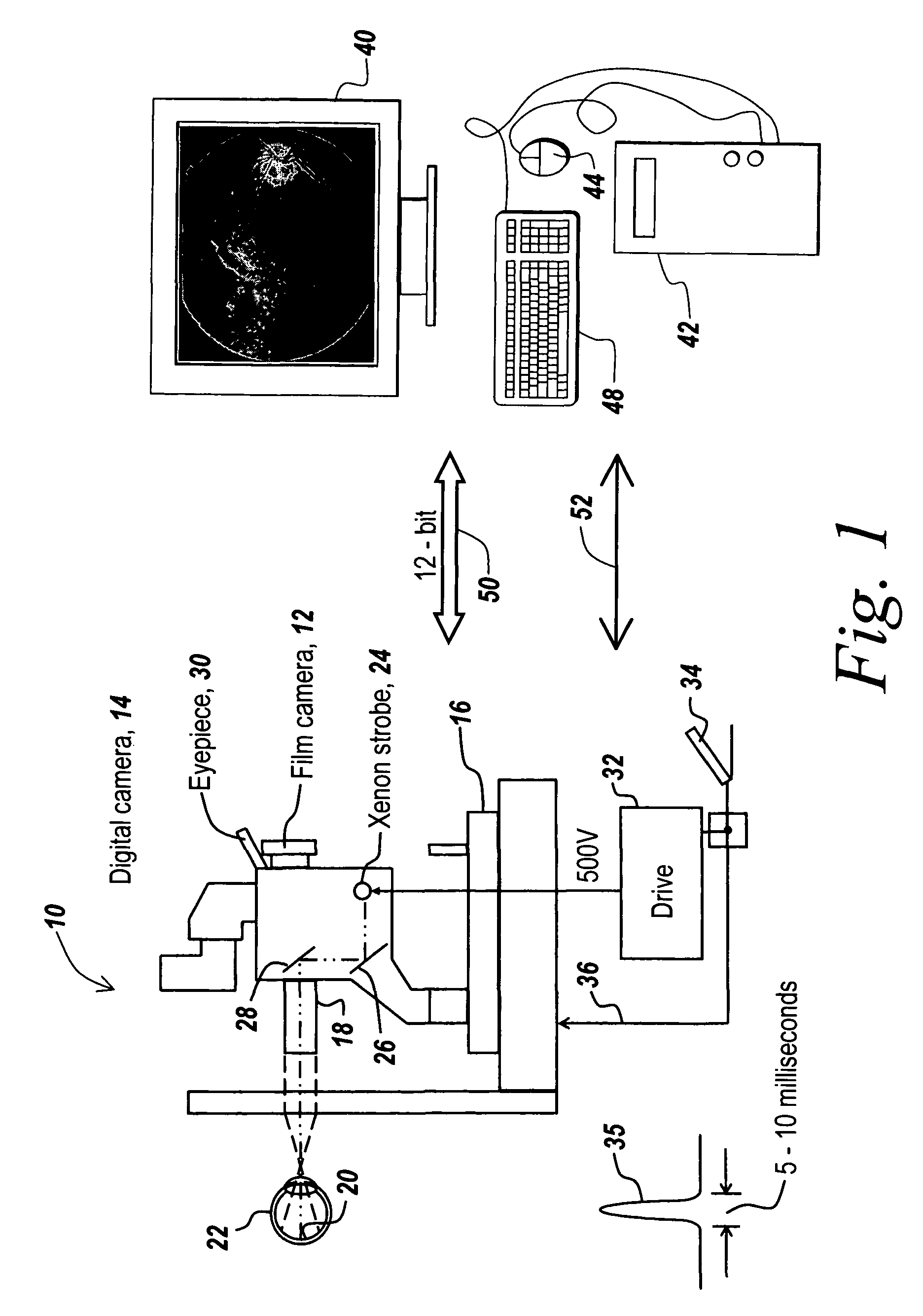
[0037]Referring now to FIG. 1, by way of background a retinal imaging camera 10 includes a film camera 12 and a digital camera 14 mounted on a stand 16 such that an imaging system 18 images the retina 20 of eye 22 onto the focal planes of cameras 12 and 14. In order to illuminate retina 20, a xenon strobe lamp 24 has its output redirected by mirrors 26 and 28 out through imaging system 18 so that the output of xenon strobe 24 illuminates retina 20. Note that an eyepiece 30 is used for focusing both the digital and film camera as well as directing the optics to the appropriate portion of the eye. In one embodiment the strobe is flashed based on toggling of a foot switch 34.

[0038]It will be appreciated that foot switch 34 is also used to control camera 10 over line 36 to take the pictures such that any shuttering and exposure for either the film camera or the digital camera is controlled responsive to foot switch 34; or is actuated automatically if desired.

[0039]Note in this figure, a...


PUM


Abstract

Driver current in digital retinal image transfer is significantly reduced for retinal cameras for reducing heat-induced dark current and resultant haze. In one embodiment line drivers are used whose current draw does not depend on data rate or frequency to eliminate the problem of high data rates creating high driver current draw. In a second embodiment the 14-MHz clock driver is inhibited by interrupting its free-running clock pulse input until such time as one wishes to output a picture from the retinal camera, at which time the clock driver draws only a quick burst of current. The result is much lower overall clock driver current draw, less heat, less dark current and less haze.

Description

FIELD OF THE INVENTION[0001]This invention relates to retinal imaging and more particularly to a method and apparatus for reducing haze.BACKGROUND OF THE INVENTION[0002]Retinal cameras that transfer digital camera images using digital transmission between the camera and the image-rendering system have been employed in the past to take the 6- to 11-megapixel digital camera outputs and transfer the data over parallel lines in a cable to follow-on processing. Thus, the images from retinal cameras are transmitted to either a local processor over for instance 10 feet, or around the world so that the digital images may be remotely displayed.[0003]There has however been a problem with haze due to the dark currents induced by circuits housed within the camera. The current draw of these circuits causes the CCD sensor array to heat up in a matter of minutes. This results in images containing haze because the sensor array in the camera has difficulty distinguishing between heat and light. It w...

Claims


Application Information

Patent Timeline
Patent Type & Authority Patents(United States)
IPC IPC(8): H04N5/217H04N5/225H04N9/64A61B3/12H04N5/361
CPCA61B3/12A61B3/145H04N5/32
Inventor CARNEVALE, MATTHEW
Owner SONOMED IP HLDG
Why Eureka
Try Eureka