Fiber chopper apparatus and method

a technology of chopper and fiber, which is applied in the direction of shearing apparatus, metal working apparatus, manufacturing tools, etc., can solve the problems of fiber breakage, fuzz build-up, serious and costly problems, etc., and achieve the effect of eliminating fiber breakag

Inactive Publication Date: 2010-11-16
JOHNS MANVILLE CORP
View PDF8 Cites 6 Cited by
  • Summary
  • Abstract
  • Description
  • Claims
  • Application Information

AI Technical Summary

Benefits of technology

[0008]The present invention includes a strand guide mounted upstream of the chopper and upstream from a strand separator roll or grooved oscillating roll as is well known, but down stream from a vertical projection of the closest fiberizer. This strand guide prevents the loose tail from swinging such that it would cause the strand to be thrown out of the strand separator roll and be pulled out of the nip between the blade roll and the back up roll or the chopper. The present invention also includes an improved starter shoe mounted on an air bearing and having a controlled rate of revolution (controlled resistance to rotation) which eliminates fiber breakage on the shoe and puts some tension into a new strand being started into the chopper to cause the strands to stay in the proper strand path.
[0009]The present invention also includes a new improved mount for an idler roll of the prior art choppers which allows for easy and fast removal and replacement of an idler roll assembly. This inventive mount, because of its improved structural integrity and integration of the components, also keeps the surface of the idler roll in better contact with the strands running on the back up roll and thus keeps the strands in the nip between the blade roll and the back up roll. The present invention also includes a strand guide insert for the protective cover guard for the working parts of the chopper which prevents the fibers from breaking and causing fuzz when a strand strikes an edge in an opening in the cover guard.
[0010]It has also been discovered that most of the good chopped strands thrown onto the floor of the fiber forming room by the chopper occurs because some chopped strands hang onto the peripheral surface of the backup roll for a fraction of a second and are then thrown off. The present invention also includes a deflector plate mounted in such a place that an edge of a deflector plate is kept very close to the peripheral surface of the back up roll and such that any chopped strands striking a working surface of the deflector plate will fall off into the flow of product. The deflector plate is preferably mounted in such a way that the top edge can be adjusted with respect to the peripheral surface of the backup roll while the chopper is operating.

Problems solved by technology

Prior art choppers occasionally fail to cut completely all the strands passing through the chopper resulting in “stringers”, fibers and strands of fiber that vary in length from a few inches to several feet.
Also, fibers break and build up fuzz on parts of the prior art choppers and periodically break loose in clumps and go into the chopped product.
A clump of fuzz is a tangled mass of one or more long fibers and since it won't disperse completely in the customers processes, most fuzz clumps may cause defects in the final products.
The industry has tried for a long time to eliminate the stringer and fuzz problems and while the frequency has been reduced, at least at times, the problems remain serious and costly.
Stringers and fuzz clumps, if present in the chopped strand cause costly defects in the products in which the chopped fiber and chopped strand are used.
Another problem with the prior art choppers is that they throw a very small percentage of good chopped fiber onto the chopper frame or onto the floor causing a housekeeping problem and reducing the material efficiency of the process.
Attempts have been made to correct this problem with little or no success.

Method used


Image

  • Fiber chopper apparatus and method
  • Fiber chopper apparatus and method
  • Fiber chopper apparatus and method

Examples


Embodiment Construction

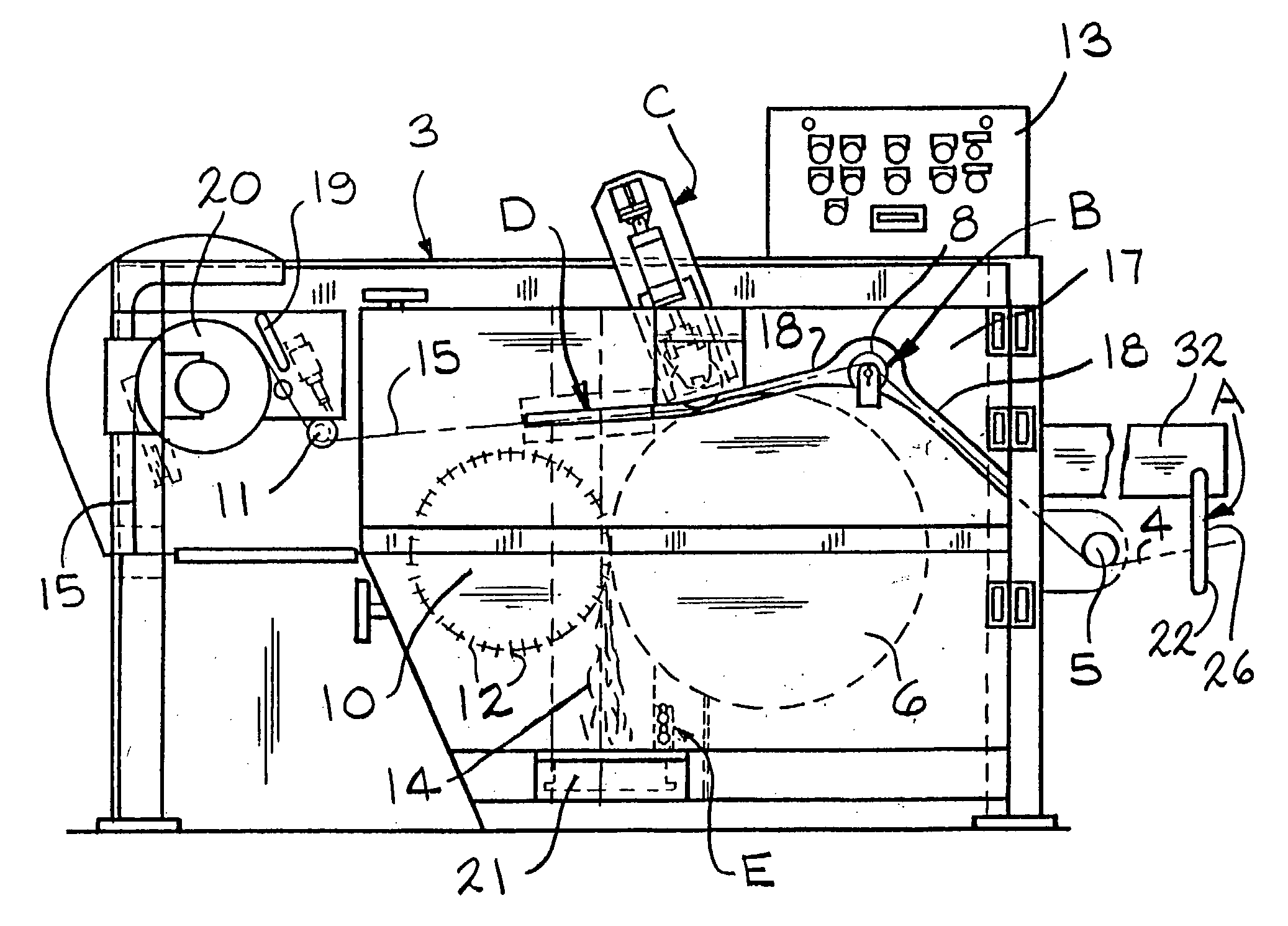
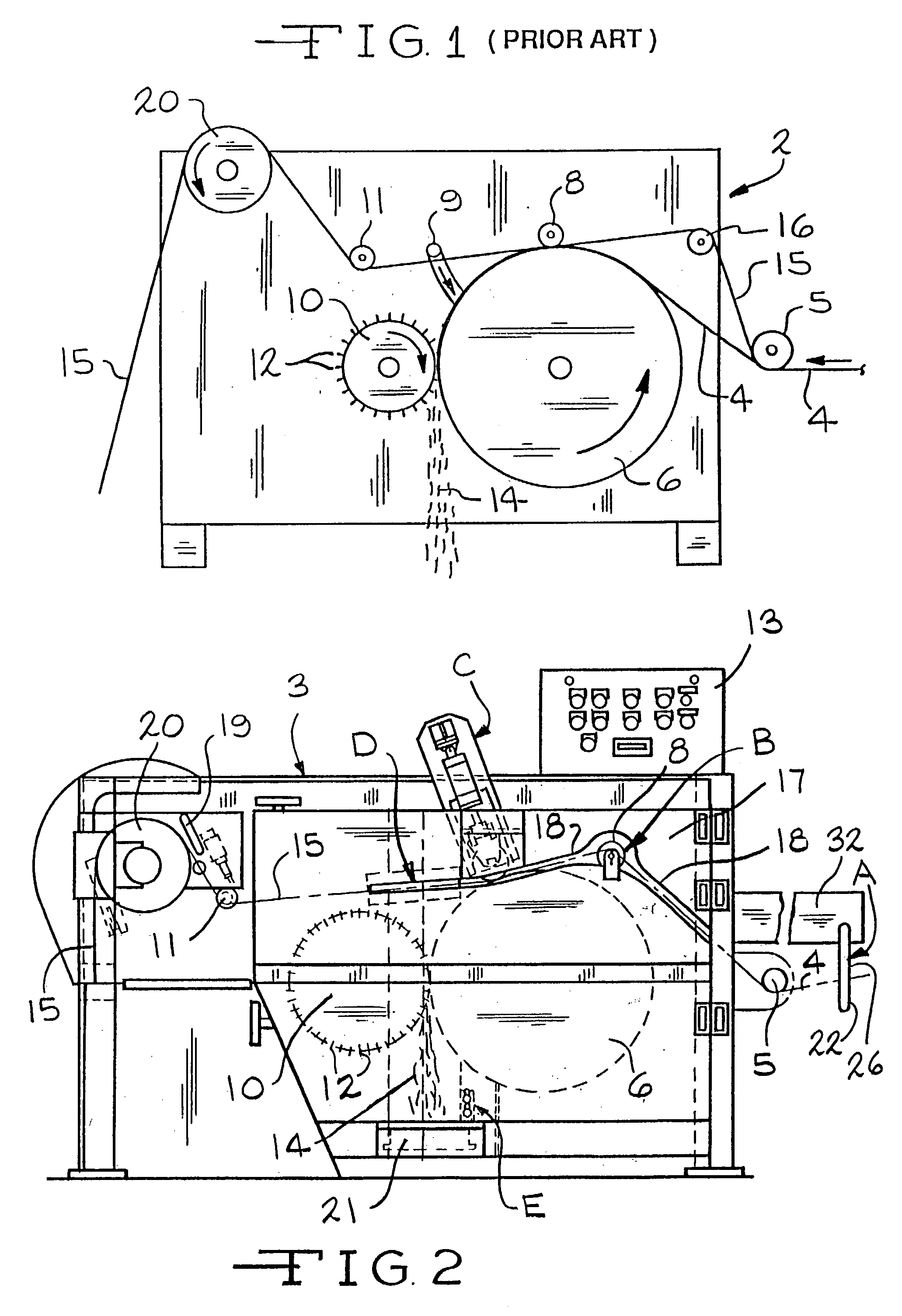
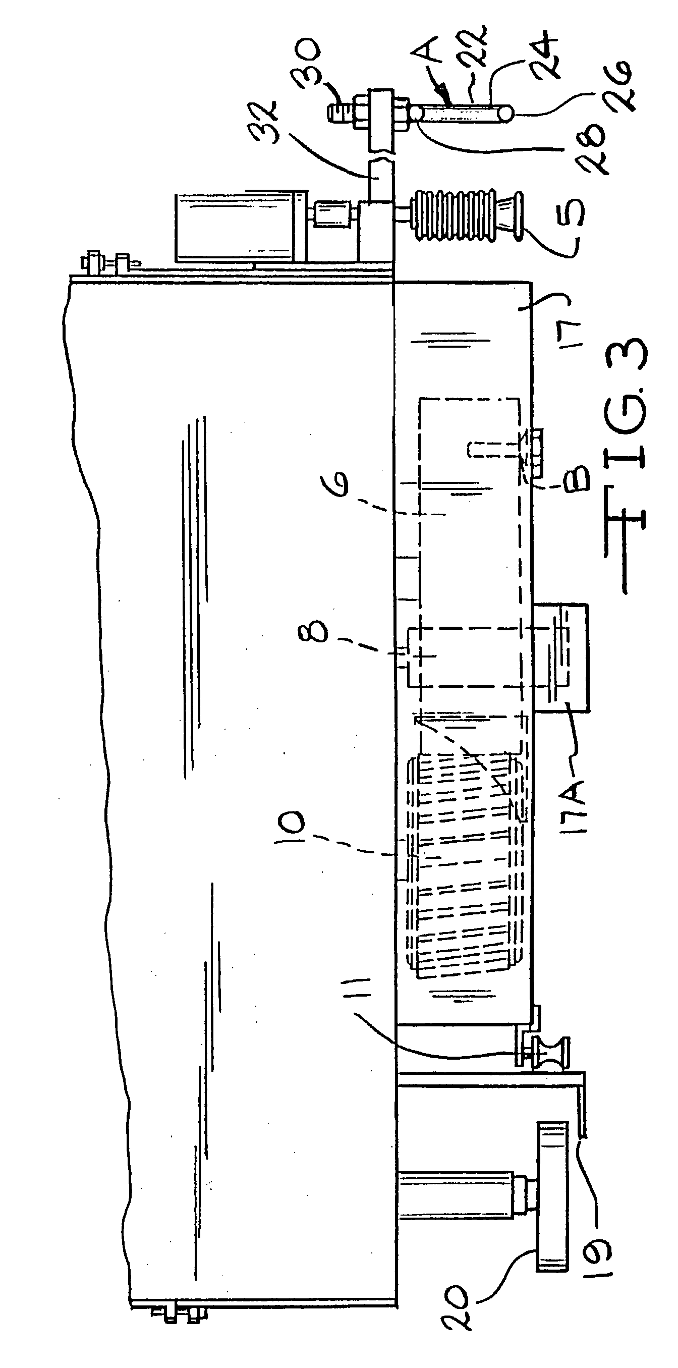
[0024]FIG. 1 shows a front view of a typical prior art chopper 2 used in making chopped glass fiber. Although the chopper will chop fibers and fiber strands of many different kinds of materials, glass fiber strands will be used for purposes of describing the invention. One or more, usually eight or more, glass strands 4, each strand containing 400-6000 or more fibers having water or an aqueous chemical sizing on their surfaces in a known manner, are pulled by a backup roll 6, in cooperation with an idler roll 8 having a knurled surface, into the chopper 2.

[0025]The strands 4 first run under a grooved separator roll 5 that can be oscillating some along its axis in a known manner, preferably with one strand in each groove, and upward and over the outer surface of the backup roll 6. The working surface of the back up roll 6 is typically made of polyurethane and is wider than the oscillating path of the glass fiber strands. The strands 4 then pass under a knurled idler roll 8 that is lo...


PUM

PropertyMeasurementUnit
diameteraaaaaaaaaa
pressuresaaaaaaaaaa
lengthaaaaaaaaaa

Abstract

A chopper for chopping fibers or fiber strands having a back up roll and a blade roll containing blades that work against a peripheral surface of the back up roll and a method of using is disclosed. The chopper has a number of improved features for reducing the frequency of long fibers or long fiber strands and fuzz from getting into the chopped product. The chopper can have one or any combination of the improvements. The improvements include a strand guide located at least two feet up stream of the chopper, a first starting roll for starting a new strand that runs on a fluid bearing that can be adjusted to control the RPM of the first starting roll, a mount for a roll that runs against the peripheral surface of said back up roll, a strand guide insert for reducing fuzz generation and for preventing fuzz from getting into the product, and a deflector plate for catching and deflecting chopped strands thrown off the back up roll into a chopped strand product chute.

Description

[0001]This application is a division of application Ser. No. 09 / 843,185, filed, Apr. 26, 2001, now U.S. Pat. No. 6,564,684, which application is a division of application Ser. No. 09 / 129,461 filed Aug. 4, 1998, now U.S. Pat. No. 6,267,035 issued Jul. 31, 2001. The present invention pertains to improvements of chopping apparatus for cutting fiber and strands of material such as mineral fiber including fiber glass, synthetic fibers including polyester or polyethylene and natural fibers including hemp and cotton, or for cutting ribbon like materials, and the method of using the improved chopper to make chopped products at high speeds of several thousand feet per minute. The apparatus is a vast improvement over the choppers used heretofore in that the improved chopper of the present invention greatly reduces and essentially eliminates stringers and fuzz in the chopped strand product and also reduces chopped fiber losses.[0002]Chopped fiber and chopped strands are used in a number of dif...

Claims


Application Information

Patent Timeline
Patent Type & Authority Patents(United States)
IPC IPC(8): B26D7/06D01G1/04
CPCD01G1/04Y10S83/913Y10S83/95Y10T83/727Y10T83/2216Y10T83/2092Y10T83/04Y10T83/4766Y10T83/6641Y10T83/7809Y10T83/4838Y10T83/739Y10T83/6648Y10T83/2209Y10T83/0515Y10T83/2083Y10T83/664
Inventor BASCOM, RANDALL CLARKHENDRICKSON, HAROLD MILESARTERBURN, RUSSELL DONOVANSANTIZO, CARLOS GILBERTOBARBER, EMERY SIDNEY
Owner JOHNS MANVILLE CORP
Why Eureka
Try Eureka