
Method for dicing semiconductor substrate

a semiconductor substrate and dicing technology, applied in the direction of semiconductor/solid-state device details, manufacturing tools, welding/soldering/cutting articles, etc., can solve the problems of difficult to completely absorb particle particles, difficult to operate semiconductor devices, and increase the size of semiconductor devices, so as to improve yield ratio, yield ratio, and yield

Inactive Publication Date: 2010-11-23
DENSO CORP
View PDF39 Cites 15 Cited by
  • Summary
  • Abstract
  • Description
  • Claims
  • Application Information

AI Technical Summary

Benefits of technology

The present patent aims to provide a device separated from a wafer, a method for processing a wafer, a semiconductor device, and a dicing device for dividing a semiconductor substrate into a plurality of chips. The device separated from a wafer includes a chip with a sidewall covered with a protection member to prevent dust and particles from being removed from the chip. The method for processing a wafer includes covering the chip with a protection member to prevent particles from being removed from the chip. The semiconductor device includes a dicing film and a laser element for forming a reforming portion in the substrate. The dicing film is mounted on an expand device to allow for easy removal of particles. The technical effects of the present patent include improved yielding ratio and quality of the chip, prevention of particles from being removed from the chip, and improved quality of the semiconductor device.

Problems solved by technology

When the dust is attached to a semiconductor device formed on a chip, the semiconductor device may malfunction.
For example, in a case where a monolithic IC as a semiconductor device is formed on the chip, when the particle is attached on the semiconductor element or a wiring in the monolithic IC, the particle may cause short-circuit.
Thus, a crack is generated at the reforming portion as the starting point, and the crack becomes larger so that the wafer is cut and separated.
Further, it is difficult to absorb the particle completely.

Method used


Image

  • Method for dicing semiconductor substrate
  • Method for dicing semiconductor substrate
  • Method for dicing semiconductor substrate

Examples


first embodiment

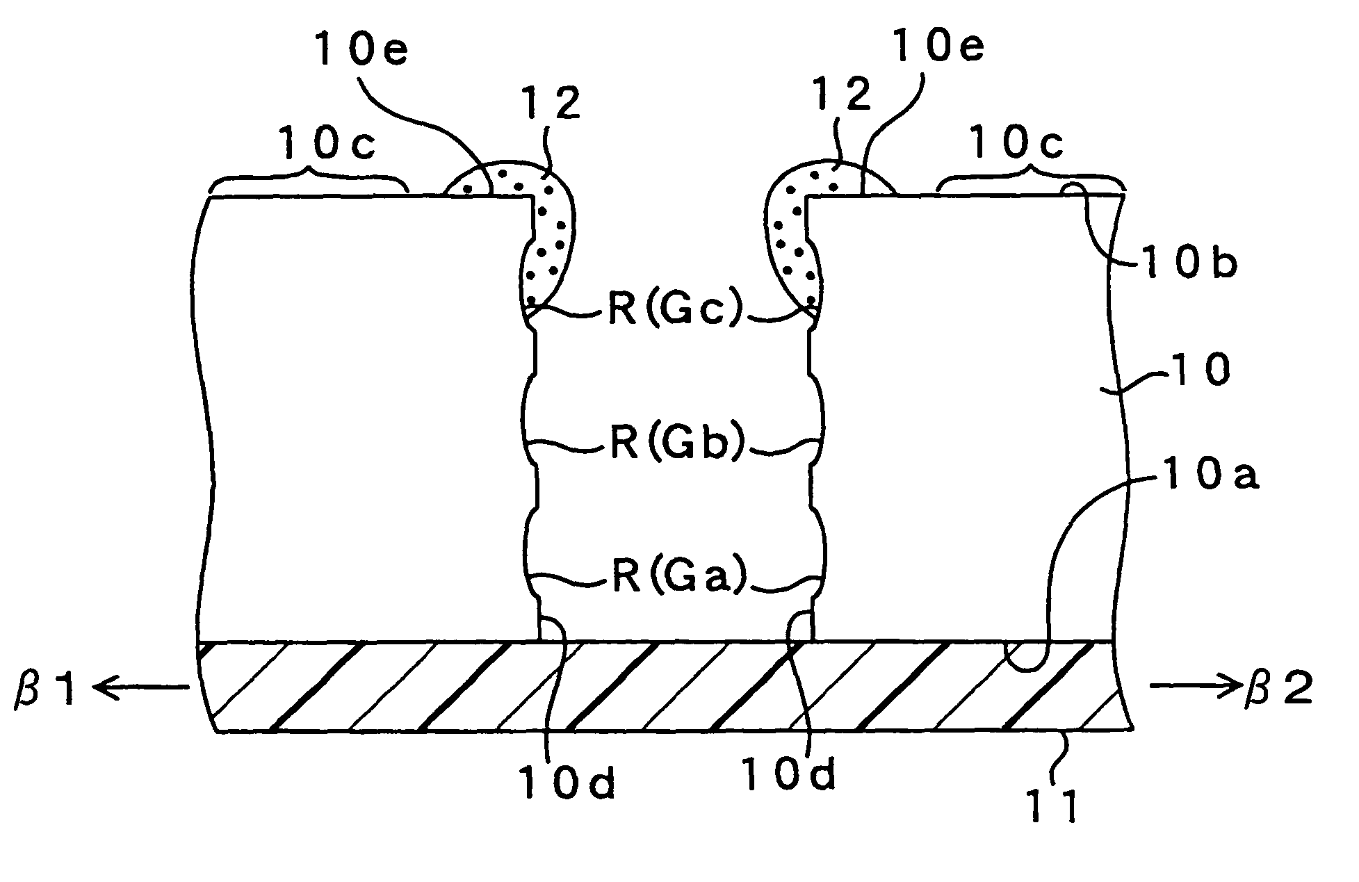
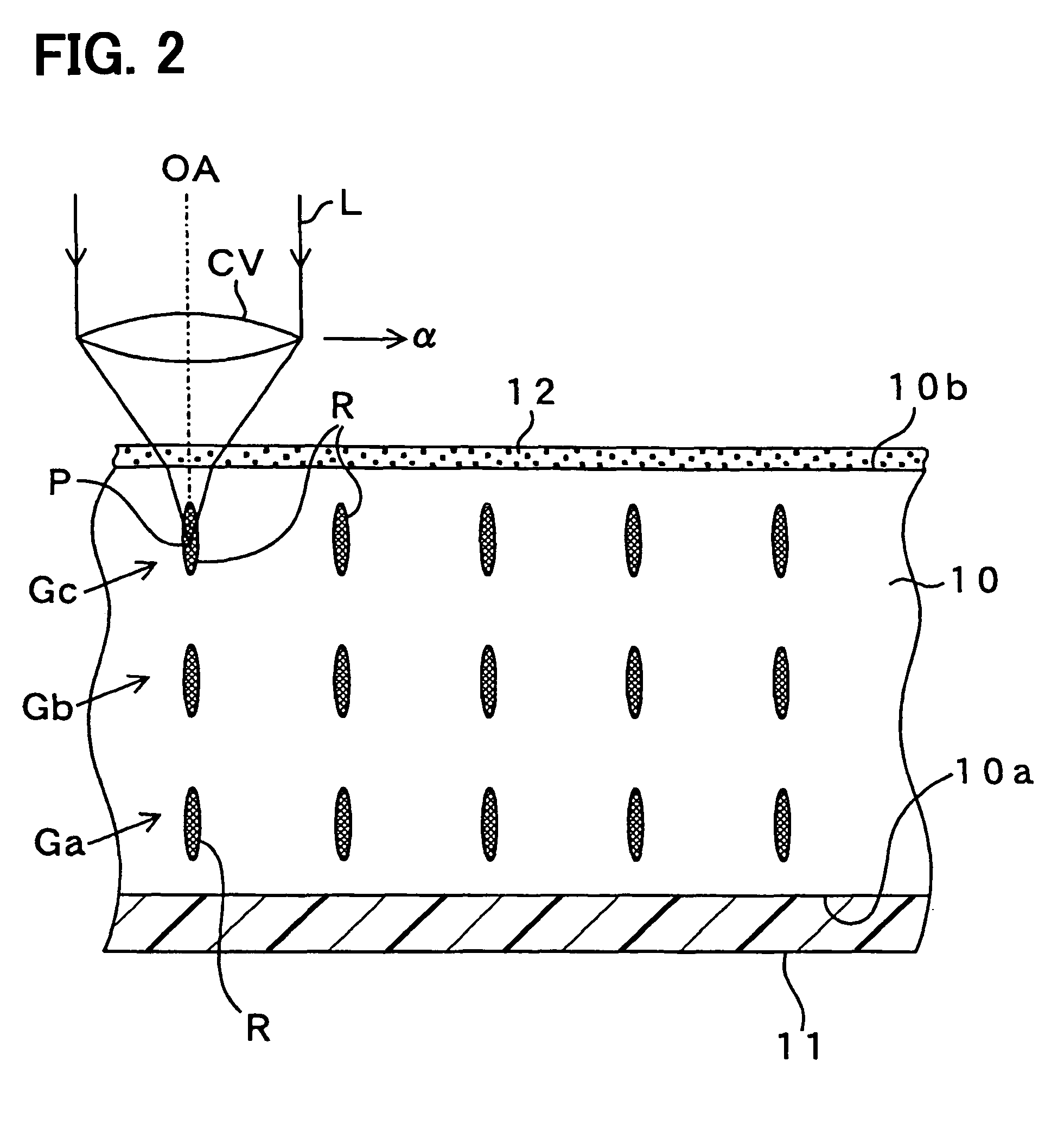
[0053]FIGS. 1A, 1B and 2 show a method for processing a wafer. Specifically, FIGS. 1A, 1B and 2 explain a step of forming a reforming portion by irradiating a laser beam on a wafer 10. The wafer 10 such as a bulk silicon wafer is made from bulk single crystal silicon, and has a backside 10a. A dicing film 11 such as a dicing seat, a dicing tape or an expandable tape is formed on the backside 10a of the wafer 10.

[0054]The dicing film 11 is made from a plastic film. The dicing film 11 is extendable by applying a force in an extendable direction and by heating. The dicing film 11 is adhered on whole area of the backside of the wafer 10 with adhesive (not shown).

[0055]A device forming region 10c is formed on the foreside 10b of the wafer 10. In the device forming region 10c, a semiconductor device (not shown) is formed. The semiconductor device is, for example, a monolithic IC, a semiconductor element, a sensor or a micro-machine. The sensor and the micro-machine are formed by a MEMS me...

second embodiment

[0114]FIGS. 4A and 4B show a method for processing the wafer 10. Specifically, FIGS. 4A and 4B show another method for forming the reforming portions R in the wafer 10. The wafer 10 includes a concavity 21 on the surface 10b of the wafer 10. The concavity 21 is disposed on the part 10e of the wafer 10, and has a U-shaped cross section with a corner. The thermoplastic member 12 is formed in the concavity 21.

[0115]When the wafer 10 is cut and separated from the cutting line K, and the melted thermoplastic member 12 falls along with the dicing surface 10d, since the thermoplastic member 12 is accommodated in the concavity 21, the melted thermoplastic member 12 does not extend on the device forming region 10c. Specifically, the melted thermoplastic member 12 does not overflow from the concavity 21, and therefore, the thermoplastic member 12 does not reach the device forming region 10c on the surface 10b of the wafer 10. Thus, all melted thermoplastic member 12 falls down into the dicing...

third embodiment

[0120]FIGS. 6A and 6B show a method for processing the wafer 10. Specifically, FIGS. 6A and 6B show further another method for forming the reforming portions R in the wafer 10.

[0121]The wafer 10 includes a pair of concavities 31a, 31b on the surface 10b of the wafer 10. Each concavity 31a, 31b are disposed between the cutting line K and the device forming region 10c, and has a U-shaped cross section with a corner. Thus, the concavities 31a, 31b are disposed in parallel to the cutting line K so that the cutting line K is sandwiched between the concavities 31a, 31b. Firstly, the thermoplastic member 12 is formed on the part 10e of the wafer 10.

[0122]When the wafer 10 is cut and separated from the cutting line K, and the melted thermoplastic member 12 falls along with the dicing surface 10d, since the concavities 31a, 31b are disposed between the part 10e of the wafer 10 and the device forming region 10c, the melted thermoplastic member 12 does not extend on the device forming region 1...


PUM

PropertyMeasurementUnit
wavelengthaaaaaaaaaa
center angleaaaaaaaaaa
pressureaaaaaaaaaa

Abstract

A device separated from a wafer includes: a chip having a sidewall, which is provided by a dicing surface of the wafer in a case where the device is separated from the wafer; and a protection member disposed on the sidewall of the chip for protecting the chip from being contaminated by a dust from the dicing surface. In the device, the dicing surface of the wafer is covered with the protection member so that the chip is prevented from contaminated with the dust.

Description

CROSS REFERENCE TO RELATED APPLICATIONS[0001]This application is based on Japanese Patent Applications No. 2005-331208 filed on Nov. 16, 2005, No. 2005-331210 filed on Nov. 16, 2005, No. 2006-173649 filed on Jun. 23, 2006, and No. 2006-288743 filed on Oct. 24, 2006, the disclosures of which are incorporated herein by reference.FIELD OF THE INVENTION[0002]The present invention relates to a semiconductor device and a method for processing a wafer.BACKGROUND OF THE INVENTION[0003]Conventionally, a processing object such as a semiconductor wafer is diced, i.e., cut and separated, by using a laser beam. This laser dicing method is disclosed in, for example, Japanese Patent No. 3408805. In this method, the laser beam is irradiated on the processing object such as a wafer to focus on the inside of the object. Thus, a reforming portion is formed in the inside of the object by multiple photon absorption effect of the laser beam. The reforming portion includes a crack, a melting region, or a ...

Claims


Application Information

Patent Timeline
Patent Type & Authority Patents(United States)
IPC IPC(8): H01L21/00
CPCB23K26/0057B23K26/009B23K26/4075B28D5/0011H01L21/67132H01L21/6835H01L21/6836H01L21/78H01L23/3192H01L2221/68327H01L2221/68336H01L2924/19041B23K2201/40H01L2924/0002H01L2924/00B23K26/40B23K26/53B23K2101/40B23K2103/50
Inventor KOMURA, ATSUSHIFUJII, TETSUOTAMURA, MUNEOASAI, MAKOTO
Owner DENSO CORP
Features
  • Generate Ideas
  • Intellectual Property
  • Life Sciences
  • Materials
  • Tech Scout
  • Unparalleled Data Quality
  • Higher Quality Content
  • 60% Fewer Hallucinations
Learn More